
User's Manual Part 3

Release8InstallationandConfigurationGuide
Issue2,November2007 Draft5forRegula toryReview 360
14. If the CMM is a CMMmicro, set the Sync Input parameter to the Sync
to Received Signal (Power Port) selection.
If the CMM is a CMM2, set the Sync Input parameter to the Sync to Received
Signal (Timing Port) selection.
end of procedure
19.11 INSTALLINGABHTIMINGSLAVE
Installing a Cyclone BHS consists of two procedures:
◦ Physically installing the BHS and performing a course alignment using the
alignment tone (Procedure 31).
◦ Verifying the BH link and finalizing alignment using review of power level and
jitter, link tests, and review of registration and session counts (Procedure 32 on
Page 361).
Procedure 31: Installing the BHS
1. Choose the best mounting location for the BHS.
2. Remove the base cover of the BHS. (See Figure 46 on Page 178.)
3. Terminate the UV outside grade Category 5 Ethernet cable with an RJ-45
connector, and connect the cable to the BHS. (See Procedure 8 on Page 192.)
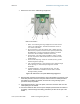
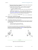
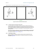
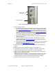
4. Attach the BHS to the arm of the Cyclone Passive Reflector dish assembly as
shown in Figure 127 on Page 350.
RECOMMENDATION:
The arm is molded to receive and properly aim the BH relative to the
aim of the dish. Use stainless steel hose clamps for the attachment.
5. Use stainless steel hose clamps or equivalent fasteners to lock the BHS into
position.
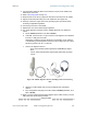
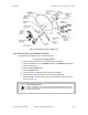
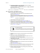
6. Remove the cover of the 300SS Surge Suppressor.
7. With the cable openings facing downward, mount the 300SS as close to the
grounding system (Protective Earth) as possible.
8. Using diagonal cutters or long nose pliers, remove the knockouts that cover the
cable openings to the 300SS.
9. Connect an Ethernet cable from the power adapter to either RJ-45 port of the
300SS.
10. Connect another Ethernet cable from the other RJ-45 port of the 300SS to the
Ethernet port of the BHS.
11. Refer to Grounding SMs on Page 172.
12. Wrap an AWG 10 (or 6mm
2
) copper wire around the Ground post of the 300SS.
13. Tighten the Ground post locking nut in the 300SS onto the copper wire.
14. Securely connect the copper wire to the grounding system (Protective Earth)
according to applicable regulations.