
User's Manual Part 3

Release8InstallationandConfigurationGuide
Issue2,November2007 Draft5forRegula toryReview 357
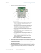
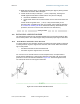
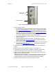
Improper dish, tube, and module positions for this case are illustrated in Figure 133.
--------------------------------------------EARTH--------------------------------------------
Figure 133: Incorrect mount with reflector dish
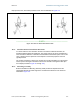
19.9.2 ModulesMountedatDifferentElevations
For cases where the other module in the link is mounted at a different elevation, the
assembly hardware allows tilt adjustment. The proper angle of tilt can be calculated as a
factor of both the difference in elevation and the distance that the link spans. Even in this
case, a plumb line and a protractor can be helpful to ensure the proper tilt. This tilt is
typically minimal.
The number of degrees to offset (from vertical) the mounting hardware leg of the support
tube is equal to the angle of elevation from the lower module to the higher module (b in
the example provided in Figure 34 on Page 146).
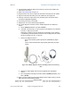
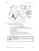
19.9.3 MountingAssembly
Both the hardware that Mounting Assembly 27RD provides for adjustment and the
relationship between the offset angle of the module and the direction of the beam are
illustrated in Figure 134.