
User's Manual Part 3

Release8InstallationandConfigurationGuide
Issue2,November2007 Draft5forRegula toryReview 356
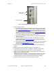
10. Briefly monitor these values, occasionally refreshing this page by clicking another
tab and then the Session Status tab again.
11. If these values are low (for example, 1, 1, and 0, respectively, meaning that
the SM registered and started a stable session once) and not changing
a. consider the installation successful.
b. monitor these values from the network office over the next several hours and
days.
If these values are greater than 1, 1, and 0, or they increase while you are
monitoring them, troubleshoot the link. (For example, recheck jitter as described
in Procedure 28: Installing the SM or recheck link efficiency as described in this
procedure, then look for sources of RF interference or obstructions.)
end of procedure
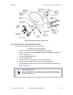
19.9 INSTALLINGAREFLECTORDISH
The internal patch antenna of the module illuminates the Cyclone Passive Reflector Dish
from an offset position. The module support tube provides the proper angle for this offset.
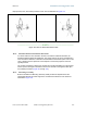
19.9.1 BothModulesMountedatSameElevation
For cases where the other module in the link is mounted at the same elevation, fasten the
mounting hardware leg of the support tube vertical for each module. When the hardware
leg is in this position
• the reflector dish has an obvious downward tilt.
• the module leg of the support tube is not vertical.
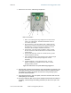
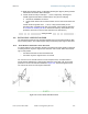
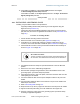
For a mount to a non-vertical structure such as a tapered tower, use a plumb line to
ensure that the hardware leg is vertical when fastened. Proper dish, tube, and module
positions for a link in this case are illustrated in Figure 132. The dish is tipped forward,
not vertical, but the focus of the signal is horizontal.
--------------------------------------------EARTH--------------------------------------------
Figure 132: Correct mount with reflector dish