
User's Manual Part 3

Release8InstallationandConfigurationGuide
Issue2,November2007 Draft5forRegula toryReview 351
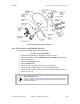
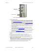
7. Remove the cover of the 300SS Surge Suppressor.
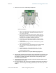
KEYTOCALLOUTS
1 Holes—for mounting the Surge Suppressor to a flat surface
(such as an outside wall). The distance between centers is
4.25 inches (108 mm).
2 RJ-45 connectors—One side (neither side is better than the
other for this purpose) connects to the Cyclone product (AP,
SM, BHM, BHS, or cluster management module). The other
connects to the AC adaptor’s Ethernet connector.
3 Ground post—use heavy gauge (10 AWG or 6 mm
2
) copper
wire for connection. Refer to local electrical codes for exact
specifications.
4 Ground Cable Opening—route the 10 AWG (6 mm
2
) ground
cable through this opening.
5 CAT-5 Cable Knockouts—route the two CAT-5 cables through
these openings, or alternatively through the Conduit
Knockouts.
6 Conduit Knockouts—on the back of the case, near the
bottom. Available for installations where cable is routed
through building conduit.
Figure 129: Internal view of Cyclone 300SS Surge Suppressor
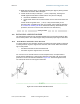
8. With the cable openings facing downward, mount the 300SS to the outside of the
subscriber premises, as close to the point where the Ethernet cable penetrates
the residence or building as possible, and as close to the grounding system
(Protective Earth) as possible.
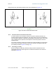
9. Using diagonal cutters or long nose pliers, remove the knockouts that cover the
cable openings to the 300SS.
10. Connect an Ethernet cable from the power adapter (located inside the residence
or building, outward through the building penetration) to either RJ-45 port of the
300SS.