
User's Manual Part 3

Release8InstallationandConfigurationGuide
Issue2,November2007 Draft5forRegula toryReview 349
19.6.6 VerifyingCMMmicroConnections
To verify the CMMmicro connections after the APs and or BHs have been installed,
perform the following steps.
Procedure 27: Verifying CMMmicro connections
1. Access the web-based interface for each AP or BH by opening
http://<ip-address
>, where the <ip-address> is the address of the individual
module.
2. In the Status page, verify that the time is expressed in GMT.
3. In the menu on the left-hand side of the web page, click on GPS Status.
4. Verify that the AP or BH is seeing and tracking satellites. (To generate the timing
pulse, the module must track at least 4 satellites.)
end of procedure
19.7 INSTALLINGANSM
Installing a Canopy SM consists of two procedures:
◦ Physically installing the SM on a residence or other location and performing a
course alignment using the alignment tone (Procedure 28).
◦ Verifying the AP to SM link and finalizing alignment using review of power level
and jitter, link tests, and review of registration and session counts (Procedure 29
on Page 353).
Procedure 28: Installing the SM
1. Choose the best mounting location for the SM.
2. Select the type of mounting hardware appropriate for this location. (For mounting
2.4, 5.2, 5.4, and 5.7 GHz SMs, Last Mile Gear offers the SMMB-1 mounting
bracket. For mounting 900 MHz SMs, Last Mile Gear offers the SMMB-2
mounting bracket.)
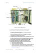
3. Remove the base cover of the SM. (See Figure 46 on Page 178.)
4. Terminate the UV outside grade Category 5 Ethernet cable with an RJ-45
connector, and connect the cable to the SM. (See Procedure 8 on Page 192.)
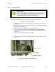
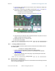
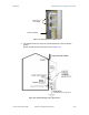
5. Optionally, attach the SM to the arm of the Cyclone Passive Reflector dish
assembly as shown in Figure 127.
RECOMMENDATION:
A reflector in this instance reduces the beamwidth to reduce
interference. The arm is molded to receive and properly aim the
module relative to the aim of the dish. Use stainless steel hose
clamps for the attachment.