
User's Manual Part 3

Release8InstallationandConfigurationGuide
Issue2,November2007 Draft5forRegula toryReview 348
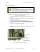
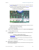
19.6.5 CablingaCMMmicro
Perform the following procedure to attach the CMMmicro cables on both ends:
Procedure 26: Cabling the CMMmicro
1. Remove the base cover from any AP or BH that is to be connected to this
CMMmicro. See Figure 46 on Page 178.
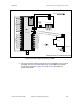
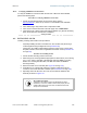
2. Review the schematic drawing inside the CMMmicro and see
Figure 70: CMMmicro connections on Page 221.
3. Note that the inserts in the bulkhead connector bushings have precut holes.
4. Remove the hard silicon spacer.
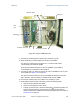
5. Route the Ethernet cables from the APs through the bulkhead connectors to the
Ethernet switch inside the CMMmicro.
6. If the BH at this site is a 30/60- or 150/300-Mbps BH
a. connect the BH outdoor unit (ODU) to the ODU port of the power indoor unit
(PIDU).
b. connect the PIDU to an unpowered port of the CMMmicro.
If the BH is of another modulation rate, route the Ethernet cables from the BH
through the bulkhead connectors to the Ethernet switch in the CMMmicro.
7. If the site has a wired network feed, route the cable into the CMMmicro and
connect it to an unpowered port on the switch.
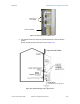
8. Mount a Cyclone surge suppressor at a low point of the network feed and
connect the surge suppressor to solid ground.
9. On the door label, record the MAC and IP addresses of the CMMmicro and all
connected equipment.
10. Consistent with practices in your company, note the above information to add
later to the company equipment database.
11. Connect the GPS coax cable from the GPS antenna to the female BNC
connector in the CMMmicro.
12. If this CMMmicro requires network connection, perform the following steps:
a. Route a network cable into the CMMmicro.
b. Connect to the uplink port on the switch.
c. Properly ground (connect to Protective Earth [PE]
) the Ethernet cable. The
Cyclone Surge Suppressor provides proper grounding for this situation.
NOTE: Instructions for installing a Cyclone Surge Suppressor are provided
as part of Procedure 28 on Page 349.
13. Connect the DC power cable to the CMMmicro.
14. Plug the DC converter into an AC receptacle.
15. Verify that the LEDs light.
end of procedure