
User's Manual Part 3

Release8InstallationandConfigurationGuide
Issue2,November2007 Draft5forRegula toryReview 345
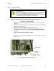
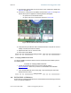
14. Connect GPS coaxial cable to the N-connector on the outside of the CMM2. See
Figure 47 on Page 180.
15. Connect AC or DC power to the CMM2, consistent with Figure 124 on Page 343.
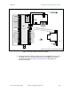
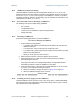
NOTE: When power is applied, the following indicators are lighted:
• the power LED on the Ethernet switch
• the green LED on the circuit board, as shown in Figure 126.
Figure 126: Port indicator LED on Ethernet switch
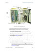
16. Verify that each port indicator LED on the Ethernet switch is lit (each AP or BH is
reliably connected to the Ethernet switch).
17. Replace the base cover on each AP or BH.
18. Close and lock the CMM2.
end of procedure
19.5.5 VerifyingCMM2Connections
To verify the CMM2 connections after the APs and or BHs have been installed, perform
the following steps:
Procedure 23: Verifying CMM2 connections
1. Access the web-based interface for each AP or BHM by opening
http://<ip-address
>, where the <ip-address> is the address of the individual
module.
2. In the General Status tab of the Home page, verify that the System Time field
displays the time in GMT.
end of procedure
19.6 INSTALLINGACMMmicro
Ensure that you comply with standard local or national electrical and climbing procedures
when you install the CMMmicro.