
User's Manual Part 3

Release8InstallationandConfigurationGuide
Issue2,November2007 Draft5forRegula toryReview 344
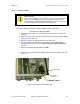
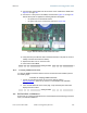
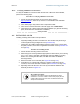
GPS
sync
Ethernet
Ethernet switch
Extra fuse
DC power connectors
AC power connectors
Figure 125: Cyclone CMM2, front view
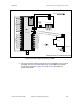
9. Connect the remaining Ethernet cables to the remaining J3 ports.
10. Route the GPS sync (serial) cables from the APs to the CMM2.
The GPS sync cables have 6-conductor RJ-11 connectors that mate to
corresponding ports inside the CMM2.
These ports are labeled J1. Eight J1 ports are available on the CMM2 to
accommodate any combination of APs and BHs.
11. Connect the GPS sync cable from the first AP or BH to the Port 1 in the J1 ports
in the CMM2. See Figure 125 on Page 344.
This port is the master GPS sync port for the CMM2 and should be connected
first in all cases. This is necessary to initialize the GPS on the CMM2.
12. Connect the remaining GPS sync cables to the remaining J1 ports.
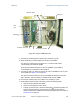
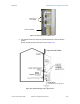
13. If this CMM2 requires network connection, perform the following steps:
a. Route a network cable into the CMM2.
b. Connect to the uplink port on the switch.
c. Properly ground (connect to Protective Earth [PE]
) the Ethernet cable. The
Cyclone Surge Suppressor provides proper grounding for this situation.
NOTE: Instructions for installing a Cyclone Surge Suppressor are provided in
Procedure 28 on Page 349.