
User's Manual Part 3

Release8InstallationandConfigurationGuide
Issue2,November2007 Draft5forRegula toryReview 341
19.5.4 CablingaCMM2
IMPORTANT!
Where you deploy CMM2s, one AP in each AP cluster must be connected to the
master port on the CMM2, and each module connected to a CMM2 must be
configured to Sync to Received Signal (Timing Port). If either is not done, then
the GPS receiver sends no sync pulse to the remaining ports.
Perform the following procedure to attach the CMM2 cables on both ends:
Procedure 22: Cabling the CMM2
1. Carefully review the practices recommended in Best Practices for Cabling on
Page 182.
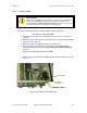
2. Remove the base cover from any AP or BH that is to be connected to this CMM2.
See Figure 46 on Page 178.
3. Remove the GPS sync cable knockout from the base cover.
4. For any AP that is to be connected to this CMM2, set the AP Sync Input
Configuration Page parameter to the Sync to Received Signal (Timing Port)
selection.
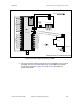
5. Review the schematic drawing inside the CMM2.
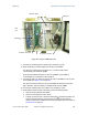
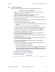
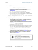
6. Set the 115-/230-volt switch in the CMM2 consistent with the power source. See
Figure 123.
115/230 V switch
AC power
connectors
Fuse receptacle
Figure 123: Location of 115-/230-volt switch