
User's Manual Part 3

Release8InstallationandConfigurationGuide
Issue2,November2007 Draft5forRegula toryReview 337
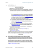
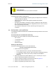
19.2 INSTALLINGANAP
To install the Cyclone AP, perform the following steps.
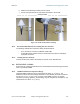
Procedure 19: Installing the AP
1. Begin with the AP in the powered-down state.
2. Choose the best mounting location for your particular application. Modules need
not be mounted next to each other. They can be distributed throughout a given
site. However, the 60° offset must be maintained. Mounting can be done with
stainless steel hose clamps or another equivalent fastener.
3. Align the AP as follows:
a. Move the module to where the link will be unobstructed by the radio horizon
and no objects penetrate the Fresnel zone. (The Cyclone System Calculator
page AntennaElevationCalcPage.xls
automatically calculates the minimum
antenna elevation that is required to extend the radio horizon to the other end
of the link. The Cyclone System Calculator page FresnelZoneCalcPage.xls
automatically calculates the Fresnel zone clearance that is required between
the visual line of sight and the top of a high-elevation object.)
b. Use a local map, compass, and/or GPS device as needed to determine the
direction that one or more APs require to each cover the intended 60° sector.
c. Apply the appropriate degree of downward tilt. (The Cyclone System
Calculator page DowntiltCalcPage.xls
automatically calculates the angle of
antenna downward tilt that is required.)
d. Ensure that the nearest and furthest SMs that must register to this AP are
within the beam coverage area. (The Cyclone System Calculator page
BeamwidthRadiiCalcPage.xls
automatically calculates the radii of the beam
coverage area.)
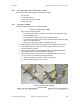
4. Using stainless steel hose clamps or equivalent fasteners, lock the AP in the
proper direction and downward tilt.
5. Remove the base cover of the AP. (See Figure 46 on Page 178.)
6. Attach the cables to the AP.
(See Procedure 5 on Page 184.)
NOTE:When power is applied to a Cyclone module or the unit is reset on the web-based
interface, the module requires approximately 25 seconds to boot. During this interval,
self-tests and other diagnostics are being performed. See Table 40 on Page 179.
end of procedure
19.3 INSTALLINGACONNECTORIZEDFLATPANELANTENNA
To install a connectorized flat panel antenna to a mast or structure, follow instructions
that the manufacturer provides. Install the antenna safely and securely, consistent with
industry practices.
The Universal Mounting Bracket available from Last Mile Gear (Part Number SMMB-1
and consisting of a mounting bracket and L-shaped aluminum tube) holds one Cyclone
module, but cannot hold both the module and a connectorized antenna. The SMMB-2 is a
heavy duty bracket that can hold both a 900-MHz module and its connectorized antenna.
See Module Support Brackets on Page 57.