
User's Manual Part 3

Release8InstallationandConfigurationGuide
Issue2,November2007 Draft5forRegulatoryReview 332
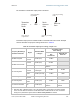
The calculation of transmitter output power is as follows:
Tra nsm itte r
Output
Po w e r
=
EI RP
Pa t c h
Antenna
Gain
Re f l e c t o r
Gain
−−
s
olve, then set
in
p
aramete
r
f
rom app
l
ica
bl
e
regulations
from the preceding
tabl
e
f
rom t
h
e prece
d
ing
table
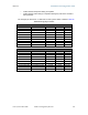
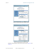
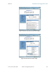
Transmitter output power is settable as dBm on the Radio tab of the module. Example
cases of transmitter output power settings are shown in Table 49.
Table 49: Transmitter output power settings, example cases
Frequency Band Range
and Antenna Scheme
Region
Maximum EIRP
in Region
Transmitter Output
Power Setting
AP, SM, or BH
with
No Reflector
SM or BH with
Reflector
900 MHz Integrated
U.S.A.
Canada
36 dBm (4 W) 24 dBm
900 MHz Connectorized
U.S.A.
Canada
36 dBm (4 W) 26 dBm
1
Australia 30 dBm (1 W)
Depends on
antenna
2.4 GHz Integrated
U.S.A.
Canada
Depends on
antenna gain
25 dBm 25 dBm
CEPT
states
20 dBm (100 mW) 12 dBm 1 dBm
5.2 GHz Integrated
U.S.A.
Canada
30 dBm (1 W) 23 dBm
5.4 GHz Integrated
CEPT
states
30 dBm (1 W) 23 dBm 5 dBm
5.7 GHz Connectorized UK 33 dBm (2 W)
Depends on
antenna
Depends on
antenna
NOTES:
1. With Mars, MTI, or Maxrad antenna. This is the default setting, and 28 dBm is the highest settable
value. The lower default correlates to 36 dBm EIRP where 10-dBi antennas are used. The default
setting for this parameter is applied whenever Set to Factory Defaults is selected.