
User's Manual Part 3

Release8OperationsGuide
Issue2,November2007 Draft5forRegula toryReview 440
3. Type into the Duration field how long (in seconds) the RF link should be tested.
4. Type into the Packet Length field the packet length at which you want the test
conducted.
5. Type into the Number of Packets field either
• the number of packets (1 to 64) for the test.
• 0 to flood the link for as long as the test is in progress.
6. Click the Start Test button.
7. In the Current Results Status block of this tab, view the results of the test.
8. Optionally
a. change the packet length.
b. repeat Steps 5 and 6.
c. compare the results to those of other tests.
end of procedure
The key fields in the test results are
• Downlink RATE and Uplink RATE, expressed in bits per second
• Downlink Efficiency and Uplink Efficiency, expressed as a percentage
A Cyclone system link is acceptable only if the efficiencies of the link test are greater than
90% in both the uplink and downlink direction, except during 2X operation. See Using
Link Efficiency to Check Received Signal Quality on Page 135. Whenever you install a
new link, execute a link test to ensure that the efficiencies are within recommended
guidelines.
The AP downlink data percentage, slot settings, other traffic in the sector, and the quality
of the RF environment all affect throughput. However, a Maximum Information Rate
(MIR) throttle or cap on the SM does not affect throughput.
27.4 USINGTHEAPEVALUATIONORBHMEVALUATIONTOOL
(SM,BHS)
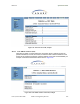
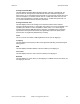
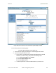
The AP Evaluation tab in the Tools web page of the SM provides information about the
AP that the SM sees. Similarly, the BHM Evaluation tab of the BHS provides information
about the BHM. An example of the AP Evaluation tab is shown in Figure 160.
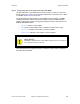
NOTE:
The data for this page can be suppressed by the SM Display of AP Evaluation
Data selection in the Security tab of the Configuration page in the AP.