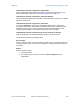
Release 8 18.4.2 Installation and Configuration Guide IP Tab of the BHM An example of an IP tab in a BHM is displayed in Figure 101. Figure 101: IP tab of BHM, example You may set the following IP Configuration page parameters. LAN1 Network Interface Configuration, IP Address Enter the non-routable IP address to be associated with the Ethernet connection on this module. (The default IP address from the factory is 169.254.1.1.) If you set and then forget this parameter, then you must both 1.
Release 8 Installation and Configuration Guide LAN1 Network Interface Configuration, Subnet Mask Enter an appropriate subnet mask for the BHM to communicate on the network. The default subnet mask is 255.255.0.0. See Allocating Subnets on Page 162. LAN1 Network Interface Configuration, Gateway IP Address Enter the appropriate gateway for the BHM to communicate with the network. The default gateway is 169.254.0.0.
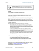
Release 8 18.4.3 Installation and Configuration Guide Radio Tab of the BHM An example of the Radio tab in a BHM is displayed in Figure 102. Figure 102: Radio tab of BHM, example In the Radio tab of the BHM, you may set the following parameters. Radio Frequency Carrier Specify the frequency for the BHM to transmit. The default for this parameter is None. (The selection labeled Factory requires a special software key file for implementation.) In a 5.
Release 8 Installation and Configuration Guide RECOMMENDATION: Note the color code that you enter. Ensure that you can readily associate this color code both with the module and with the other data that you store about the module. Sector ID You can optionally enter an identifier to distinguish this link. Downlink Data The operator specifies the percentage of the aggregate (uplink and downlink total) throughput that is needed for the downlink. The default for this parameter is 50%.
Release 8 Installation and Configuration Guide Save Changes When you click this button, any changes that you made on the IP Configuration page are recorded in flash memory. However, these changes do not apply until the next reboot of the module. Reboot When you click this button 1. the module reboots. 2. any changes that you saved by a click of the Save Changes button are implemented.
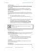
Release 8 18.4.4 Installation and Configuration Guide SNMP Tab of the BHM An example of the SNMP tab in a BHM is displayed in Figure 103. Figure 103: SNMP tab of BHM, example In the SNMP tab of the BHM, you may set the following parameters.
Release 8 Installation and Configuration Guide Community String Specify a control string that allows Prizm or a Network Management Station (NMS) to access the module through SNMP. No spaces are allowed in this string. The default string is Cyclone. The Community String value is clear text and is readable by a packet monitor. Additional security derives from the configuration of the Accessing Subnet, Trap Address, and Permission parameters.
Release 8 Installation and Configuration Guide Site Name Specify a string to associate with the physical module. This parameter is written into the sysName SNMP MIB-II object and can be polled by an NMS. The buffer size for this field is 128 characters. Site Contact Enter contact information for the module administrator. This parameter is written into the sysContact SNMP MIB-II object and can be polled by an NMS. The buffer size for this field is 128 characters.
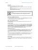
Release 8 18.4.5 Installation and Configuration Guide Security Tab of the BHM An example of the Security tab in a BHM is displayed in Figure 104. Figure 104: Security tab of BHM, example In the Security tab of the BHM, you may set the following parameters. Authentication Mode Specify whether the BHM should require the BHS to authenticate. Authentication Key Only if you set the BHM in the previous parameter to require authentication, specify the key that the BHS should use when authenticating.
Release 8 Installation and Configuration Guide Encryption Specify the type of air link security to apply to this BHM: • Encryption Disabled provides no encryption on the air link. This is the default mode. • Encryption Enabled provides encryption, using a factory-programmed secret key that is unique for each module. NOTE: In any BH link where encryption is enabled, the BHS briefly drops registration and re-registers in the BHM every 24 hours to change the encryption key.
Release 8 Installation and Configuration Guide Reboot When you click this button 1. the module reboots. 2. any changes that you saved by a click of the Save Changes button are implemented. 18.4.6 DiffServe Tab of the BHM An example of the DiffServe tab in a BHM is displayed in Figure 105.
Release 8 Installation and Configuration Guide In the DiffServe tab of the BHM, you may set the following parameters. CodePoint 1 through CodePoint 47 The default priority value for each settable CodePoint is shown in Figure 113. Priorities of 0 through 3 map to the low-priority channel; 4 through 7 to the high-priority channel. The mappings are the same as 802.1p VLAN priorities. Consistent with RFC 2474 CodePoint 0 is predefined to a fixed priority value of 0 (low-priority channel).
Release 8 18.4.7 Installation and Configuration Guide Unit Settings Tab of the BHM An example of the Unit Settings tab of the BHM is displayed in Figure 106. Figure 106: Unit Settings tab of BHM, example The Unit Settings tab of the BHM contains an option for how the BHM should react when it detects a connected override plug. You may set this option as follows. Set to Factory Defaults Upon Default Plug Detection If Enabled is checked, then an override/default plug functions as a default plug.
Release 8 Installation and Configuration Guide Save Changes When you click this button, any changes that you made on the Configuration page are recorded in flash memory. However, these changes do not apply until the next reboot of the module. Reboot When you click this button 1. the module reboots. 2. any changes that you saved by a click of the Save Changes button are implemented.
Release 8 Installation and Configuration Guide 18.5 CONFIGURING A BH TIMING SLAVE FOR THE DESTINATION If an ADMINISTRATOR-level password has been set in the BHS, you must log into the module before you can configure its parameters. See Managing Module Access by Passwords on Page 377. 18.5.1 General Tab of the BHS An example of the General tab in a BHS is displayed in Figure 107. Figure 107: General tab of BHS, example In the General tab of the BHS, you may set the following parameters.
Release 8 Installation and Configuration Guide Timing Mode Select Timing Slave. This BH will receive sync from another source. Whenever you toggle this parameter to Timing Slave from Timing Master, you should also do the following: 1. Make no other changes in this or any other interface page. 2. Save this change of timing mode. 3. Reboot the BH. RESULT: The set of interface web pages that is unique to a BHS is made available.
Release 8 Installation and Configuration Guide SM Power Up Mode With No 802.3 Link Specify the default mode in which this BHS will power up when it senses no Ethernet link. Select either • Power Up in Aim Mode—the BHS boots in an aiming mode. When the BHS senses an Ethernet link, this parameter is automatically reset to Power Up in Operational Mode. When the BHS senses no Ethernet link within 15 minutes after power up, the BHS carrier shuts off.
Release 8 18.5.2 Installation and Configuration Guide IP Tab of the BHS An example of the IP tab in a BHS is displayed in Figure 108. Figure 108: IP tab of BHS, example In the IP tab of the BHS, you may set the following parameters. LAN1 Network Interface Configuration, IP Address Enter the non-routable IP address to associate with the Ethernet connection on this BHS. (The default IP address from the factory is 169.254.1.1.) If you set and then forget this parameter, then you must both 1.
Release 8 Installation and Configuration Guide LAN1 Network Interface Configuration, Subnet Mask Enter an appropriate subnet mask for the BHS to communicate on the network. The default subnet mask is 255.255.0.0. See Allocating Subnets on Page 162. LAN1 Network Interface Configuration, Gateway IP Address Enter the appropriate gateway for the BHS to communicate with the network. The default gateway is 169.254.0.0.
Release 8 18.5.3 Installation and Configuration Guide Radio Tab of the BHS An example of the Radio tab in a BHS is displayed in Figure 109. Figure 109: Radio tab of BHS, example In the Radio tab of the BHS, you may set the following parameters. Custom Radio Frequency Scan Selection List Specify the frequency that the BHS should scan to find the BHM. The frequency band of the BHs affects what channels you select. IMPORTANT! In the 2.
Release 8 Installation and Configuration Guide channel. If you select only one, then the module limits the scan to that channel. Since the frequencies that this parameter offers for each of these two bands are 5 MHz apart, a scan of all channels does not risk establishment of a poor-quality link as in the 2.4-GHz band. Nevertheless, this can risk establishment of a link to the wrong BHM. A list of channels in the band is provided in Considering Frequency Band Alternatives on Page 136.
Release 8 Installation and Configuration Guide The Radio tab also provides the following buttons. Save Changes When you click this button, any changes that you made on this tab are recorded in flash memory. However, these changes do not apply until the next reboot of the module. Reboot When you click this button 1. the module reboots. 2. any changes that you saved by a click of the Save Changes button are implemented.
Release 8 18.5.4 Installation and Configuration Guide SNMP Tab of the BHS An example of the SNMP tab in a BHS is displayed in Figure 110. Figure 110: SNMP tab of BHS, example In the SNMP tab of the BHS, you may set the following parameters. Community String Specify a control string that allows Prizm or an NMS (Network Management Station) to access MIB information about this BHS. No spaces are allowed in this string. The default string is Cyclone.
Release 8 Installation and Configuration Guide The Community String value is clear text and is readable by a packet monitor. Additional security derives from the configuration of the Accessing Subnet, Trap Address, and Permission parameters. Accessing Subnet Specify the addresses that are allowed to send SNMP requests to this BHS. Prizm or the NMS has an address that is among these addresses (this subnet). You must enter both • The network IP address in the form xxx.xxx.xxx.
Release 8 Installation and Configuration Guide The SNMP tab also provides the following buttons. Save Changes When you click this button, any changes that you made on the Configuration page are recorded in flash memory. However, these changes do not apply until the next reboot of the module. Reboot When you click this button 1. the module reboots. 2. any changes that you saved by a click of the Save Changes button are implemented. 18.5.
Release 8 Installation and Configuration Guide Low Priority Downlink CIR See 18.5.6 ◦ Committed Information Rate on Page 86 ◦ Setting the Configuration Source on Page 295. Security Tab of the BHS An example of the Security tab in a BHS is displayed in Figure 112. Figure 112: Security tab of BHS, example In the Security tab of the BHS, you may set the following parameters.
Release 8 Installation and Configuration Guide Select Key The Use Default Key selection specifies that the link should continue to use the automatically generated authentication key. See Authentication Manager Capability on Page 389. The Use Key above selection specifies the 32-digit hexadecimal key that is permanently stored on both the BHS and the BHM. Web, Telnet, FTP Session Timeout Enter the expiry in seconds for remote management sessions via HTTP, telnet, or ftp access to the BHS.
Release 8 18.5.7 Installation and Configuration Guide DiffServe Tab of the BHS An example of the DiffServe tab in a BHS is displayed in Figure 113.
Release 8 Installation and Configuration Guide You may set the following Differentiated Services Configuration page parameters. CodePoint 1 through CodePoint 47 The default priority value for each settable CodePoint is shown in Figure 113. Priorities of 0 through 3 map to the low-priority channel; 4 through 7 to the high-priority channel. The mappings are the same as 802.1p VLAN priorities. Consistent with RFC 2474 • CodePoint 49 through CodePoint 55 • • CodePoint 57 through CodePoint 63 18.5.
Release 8 Installation and Configuration Guide Set to Factory Defaults Upon Default Plug Detection If Enabled is checked, then an override/default plug functions as a default plug. When the module is rebooted with the plug inserted, it can be accessed at the IP address 169.254.1.1 and no password, and all parameter values are reset to defaults.
Release 8 Installation and Configuration Guide • confirm that the initial power setting is compliant. • confirm that the power setting is compliant following any reset of the module to factory defaults. The total gain per antenna in 5.2 GHz and 5.4 GHz Cyclone radios is stated in Table 48. Table 48: Total gain per antenna Cyclone 5.
Release 8 Installation and Configuration Guide The calculation of transmitter output power is as follows: from applicable regulations Transmitter = Output Power EIRP from the preceding table Patch Antenna Gain − Reflec tor Gain − from the preceding table solve, then set in parameter Transmitter output power is settable as dBm on the Radio tab of the module. Example cases of transmitter output power settings are shown in Table 49.
Release 8 Installation and Configuration Guide 19 INSTALLING COMPONENTS RECOMMENDATION: Use shielded cable for all Cyclone infrastructure connections associated with BHs, APs, and CMMs. The environment that these modules operate in often has significant unknown or varying RF energy. Operator experience consistently indicates that the additional cost of shielded cables is more than compensated by predictable operation and reduced costs for troubleshooting and support. 19.
Release 8 Installation and Configuration Guide Figure 115: PDA Quick Status tab, example An example of the Spectrum Analyzer tab for PDAs is displayed in Figure 116. For additional information about the Spectrum Analyzer feature, see Monitoring the RF Environment on Page 369. Figure 116: PDA Spectrum Analyzer tab of SM, example Examples of the Spectrum Results and Information tabs for PDAs are shown in Figure 117 and Figure 118.
Release 8 Installation and Configuration Guide Figure 117: PDA Spectrum Results tab of SM, example Figure 118: PDA Information tab of SM, example Examples of the AP Evaluation and Aim tabs for PDAs are shown in Figure 119 and Figure 120.
Release 8 Installation and Configuration Guide Figure 119: PDA AP Evaluation tab of SM, example Figure 120: PDA Aim tab of SM, example Issue 2, November 2007 Draft 5 for Regulatory Review 336
Release 8 Installation and Configuration Guide 19.2 INSTALLING AN AP To install the Cyclone AP, perform the following steps. Procedure 19: Installing the AP 1. Begin with the AP in the powered-down state. 2. Choose the best mounting location for your particular application. Modules need not be mounted next to each other. They can be distributed throughout a given site. However, the 60° offset must be maintained. Mounting can be done with stainless steel hose clamps or another equivalent fastener. 3.
Release 8 Installation and Configuration Guide IMPORTANT! Connectorized antennas require professional installation. The professional installer is responsible for • selection of an antenna that the regulatory agency has approved for use with the Cyclone 900-MHz AP and SM. • setting of the gain consistent with regulatory limitations and antenna specifications. • ensuring that the polarity—horizontal or vertical—is identical on both ends of the link.
Release 8 Installation and Configuration Guide 6. Slide the lock washers (provided) onto the U-bolts. 7. Use the nuts (provided) to securely fasten the bracket to the U-bolts. end of procedure Figure 121: Detail of GPS antenna mounting 19.4.1 Recommended Materials for Cabling the GPS Antenna The following materials are required for cabling the GPS antenna: 19.4.2 • up to 100 feet (30.
Release 8 19.5.2 Installation and Configuration Guide Recommended Tools for Mounting a CMM2 The following tools may be needed for mounting the CMM2: 19.5.3 • 3/8” nut driver • 12” adjustable wrench • 14-mm wrench for pole-mounting • needle-nose pliers Mounting a CMM2 Perform the following procedure to mount the CMM2. Procedure 21: Mounting the CMM2 1. Ensure that the mounting position • is not further than 328 feet (100 meters) of cable from the furthest AP or BH that the CMM2 will serve.
Release 8 19.5.4 Installation and Configuration Guide Cabling a CMM2 IMPORTANT! Where you deploy CMM2s, one AP in each AP cluster must be connected to the master port on the CMM2, and each module connected to a CMM2 must be configured to Sync to Received Signal (Timing Port). If either is not done, then the GPS receiver sends no sync pulse to the remaining ports. Perform the following procedure to attach the CMM2 cables on both ends: Procedure 22: Cabling the CMM2 1.
Release 8 Installation and Configuration Guide CAUTION! Failure to set the 115-/230-volt switch correctly can result in damage to equipment. IMPORTANT! The AC power connectors are labeled N for Neutral, L for Line, and PE for Protective Earth (PE) or ground. The maximum thickness of wire to be used is 4 mm2 or 12 AWG. 7. Route the Ethernet cables from the APs and or BHs to the CMM2. The strain relief plugs on the CMM2 have precut holes.
Release 8 Installation and Configuration Guide TO DOOR GROUND BT-0488-011 BT-0563-XXX 8 BT-0563-XXX BLK GRN WHT BT-0588 7 - + GPS Receiver UPLINK PORT: NON-CANOPY ETHERNET DEVICES + + - + BLK Remove 8 8 BT-0556-008 TO J2 GRN Interconnect Board BT-0562-XXX BT-0556-008 Master 1 PWR LED BT-0556-008 2 BT-0563-XXX BT-0556-008 WHT GRN BT-0563-XXX BT-0556-008 3 WHT BLK BLK BT-0556-008 4 BT-0563-XXX BT-0556-008 BT-0563-XXX ETHERNET SWITCH PORTS BT-0556-008 BT-0563-XXX 5
Release 8 Installation and Configuration Guide Ethernet switch Extra fuse GPS sync Ethernet DC power connectors AC power connectors Figure 125: Cyclone CMM2, front view 9. Connect the remaining Ethernet cables to the remaining J3 ports. 10. Route the GPS sync (serial) cables from the APs to the CMM2. The GPS sync cables have 6-conductor RJ-11 connectors that mate to corresponding ports inside the CMM2. These ports are labeled J1.
Release 8 Installation and Configuration Guide 14. Connect GPS coaxial cable to the N-connector on the outside of the CMM2. See Figure 47 on Page 180. 15. Connect AC or DC power to the CMM2, consistent with Figure 124 on Page 343. NOTE: When power is applied, the following indicators are lighted: • the power LED on the Ethernet switch • the green LED on the circuit board, as shown in Figure 126. Figure 126: Port indicator LED on Ethernet switch 16.
Release 8 19.6.1 Installation and Configuration Guide CMMmicro Temperature Range Install the CMMmicro outside only when temperatures are above –4° F (–20° C). The bulkhead connector and the bushings and inserts in the bulkhead connector are rated for the full –40° to +131° F (–40° to +55° C) range of the CMMmicro. However, for dynamic operations (loosening, tightening, and inserting), they are compliant at, and rated for, only temperatures at or above –4° F (–20° C). 19.6.
Release 8 Installation and Configuration Guide WARNING! Although the output of the power converter is 24 V, the 100-W power rating classifies the converter as a Class 2 electric device. For this reason, whenever you work on power in the CMMmicro, you must first disconnect the DC converter from the AC power source. Perform the following procedure to install the provided power supply. Procedure 25: Installing the Power Supply for the CMMmicro 1.
Release 8 19.6.5 Installation and Configuration Guide Cabling a CMMmicro Perform the following procedure to attach the CMMmicro cables on both ends: Procedure 26: Cabling the CMMmicro 1. Remove the base cover from any AP or BH that is to be connected to this CMMmicro. See Figure 46 on Page 178. 2. Review the schematic drawing inside the CMMmicro and see Figure 70: CMMmicro connections on Page 221. 3. Note that the inserts in the bulkhead connector bushings have precut holes. 4.
Release 8 19.6.6 Installation and Configuration Guide Verifying CMMmicro Connections To verify the CMMmicro connections after the APs and or BHs have been installed, perform the following steps. Procedure 27: Verifying CMMmicro connections 1. Access the web-based interface for each AP or BH by opening http://, where the is the address of the individual module. 2. In the Status page, verify that the time is expressed in GMT. 3.
Release 8 Installation and Configuration Guide Stainless steel hose clamps Reflector dish arm Figure 127: SM attachment to reflector arm 6. Use stainless steel hose clamps or equivalent fasteners to lock the SM into position. NOTE: The SM grounding method is shown in Figure 128.
Release 8 Installation and Configuration Guide 7. Remove the cover of the 300SS Surge Suppressor. KEY TO CALLOUTS 1 Holes—for mounting the Surge Suppressor to a flat surface (such as an outside wall). The distance between centers is 4.25 inches (108 mm). 2 RJ-45 connectors—One side (neither side is better than the other for this purpose) connects to the Cyclone product (AP, SM, BHM, BHS, or cluster management module). The other connects to the AC adaptor’s Ethernet connector.
Release 8 Installation and Configuration Guide 11. Connect another Ethernet cable from the other RJ-45 port of the 300SS to the Ethernet port of the SM. 12. Refer to Grounding SMs on Page 172. 13. Wrap an AWG 10 (or 6mm2) copper wire around the Ground post of the 300SS. 14. Tighten the Ground post locking nut in the 300SS onto the copper wire. 15. Securely connect the copper wire to the grounding system (Protective Earth) according to applicable regulations. 16. Connect a ground wire to the 300SS. 17.
Release 8 Installation and Configuration Guide 19.8 VERIFYING AN AP‐SM LINK To verify the AP-SM link after the SM has been installed, perform the following steps. Procedure 29: Verifying performance for an AP-SM link 1. Using a computer (laptop, desktop, PDA) connected to the SM, open a browser and access the SM using the default IP address of http://169.254.1.1 (or the IP address configured in the SM, if one has been configured.) 2.
Release 8 Installation and Configuration Guide 6. If these link tests fail to consistently show 90% or greater efficiency in 1X operation or 50 to 60% efficiency in 2X, troubleshoot the link, using the data as follows: • If the downlink is consistently 90% efficient, but the uplink is only 40%, this indicates trouble for the SM transmitting to the AP. Have link tests performed for nearby SMs. If their results are similar, investigate a possible source of interference local at the AP.
Release 8 Installation and Configuration Guide Figure 131: AP/SM link status indications in the AP Session Status tab 8. Find the Session Count line under the MAC address of the SM. 9. Check and note the values for Session Count, Reg Count, and Re-Reg Count.
Release 8 Installation and Configuration Guide 10. Briefly monitor these values, occasionally refreshing this page by clicking another tab and then the Session Status tab again. 11. If these values are low (for example, 1, 1, and 0, respectively, meaning that the SM registered and started a stable session once) and not changing a. consider the installation successful. b. monitor these values from the network office over the next several hours and days.
Release 8 Installation and Configuration Guide Improper dish, tube, and module positions for this case are illustrated in Figure 133. --------------------------------------------EARTH-------------------------------------------Figure 133: Incorrect mount with reflector dish 19.9.2 Modules Mounted at Different Elevations For cases where the other module in the link is mounted at a different elevation, the assembly hardware allows tilt adjustment.
Release 8 Installation and Configuration Guide Figure 134: Mounting assembly, exploded view 19.10 INSTALLING A BH TIMING MASTER To install the Cyclone BHM, perform the following steps: Procedure 30: Installing the BHM 1. Access the General tab of the Configuration page in the BHM. 2. If this is a 20-Mbps BH, set the 2X Rate parameter to Disabled (temporarily for easier course aiming). 3. Click the Save Changes button. 4. Click the Reboot button. 5.
Release 8 Installation and Configuration Guide Stainless steel hose clamps Reflector dish arm Figure 135: BH attachment to reflector arm 8. Align the BHM as follows: a. Move the module to where the link will be unobstructed by the radio horizon and no objects penetrate the Fresnel zone. (The Cyclone System Calculator page AntennaElevationCalcPage.xls automatically calculates the minimum antenna elevation that is required to extend the radio horizon to the other end of the link.
Release 8 Installation and Configuration Guide 14. If the CMM is a CMMmicro, set the Sync Input parameter to the Sync to Received Signal (Power Port) selection. If the CMM is a CMM2, set the Sync Input parameter to the Sync to Received Signal (Timing Port) selection. end of procedure 19.11 INSTALLING A BH TIMING SLAVE Installing a Cyclone BHS consists of two procedures: ◦ Physically installing the BHS and performing a course alignment using the alignment tone (Procedure 31).
Release 8 Installation and Configuration Guide 15. Connect a ground wire to the 300SS. 16. Replace the cover of the 300SS surge suppressor. 17. For coarse alignment of the BHS, use the Audible Alignment Tone feature as follows: a. If the Configuration web page of the BHS contains a 2X Rate parameter, set it to Disable. b. At the BHS, connect the RJ-11 6-pin connector of the Alignment Tool Headset (shown in Figure 130 on Page 352) to the RJ-11 utility port of the SM.
Release 8 Installation and Configuration Guide IMPORTANT: The received Power Level is shown in dBm and should be maximized. Jitter should be minimized. However, better/lower jitter should be favored over better/higher dBm.
Release 8 Installation and Configuration Guide Figure 136: Session Status tab of BHM 8. Find the Session Count line under the MAC address of the BHS. 9. Check and note the values for Session Count, Reg Count, and Re-Reg Count. 10. Briefly monitor these values, occasionally refreshing this page by clicking another tab and then the Session Status tab again. 11.
Release 8 Installation and Configuration Guide 20 VERIFYING SYSTEM FUNCTIONALITY To verify system functionality after the APs and or BHs have been installed, perform the following steps. Procedure 33: Verifying system functionality 1. For each installed AP, use a computer or PDA connected to an SM set to a compatible configuration (frequency and color code, for example) and verify link functionality. 2.
Release 8 Operations Guide OPERATIONS GUIDE Issue 2, November 2007 Draft 5 for Regulatory Review 367
Release 8 Operations Guide 21 GROWING YOUR NETWORK Keys to successfully growing your network include • monitoring the RF environment. • considering software release compatibility. • redeploying modules appropriately and quickly. 21.1 MONITORING THE RF ENVIRONMENT Regardless of whether you are maintaining or growing your network, you may encounter new RF traffic that can interfere with your current or planned equipment.
Release 8 Operations Guide automatically fully displayed and refreshed. (Setting the “Auto Refresh” time back to 0 will disable refresh.) 21.1.2 Graphical Spectrum Analyzer Display (Not available for Cyclone OFDM) An SM/BHS displays the graphical spectrum analyzer. An example of the Spectrum Analyzer tab is shown in Figure 137. Figure 137: Spectrum Analyzer tab of SM, example Colors in the display have the following meanings: • Green bars show the most recent measurements.
Release 8 Operations Guide To transform the AP into an SM for spectrum analysis and then return the device to an AP, perform the following steps. Procedure 34: Using the Spectrum Analyzer in AP feature 1. Connect to the wired Ethernet interface of the AP. 2. Access the General tab of the Configuration page in the AP. 3. Set the Device Setting parameter to SM. 4. Click the Save Changes button. 5. Click the Reboot button. 6.
Release 8 Operations Guide 21.2 CONSIDERING SOFTWARE RELEASE COMPATIBILITY Within the same Cyclone network, modules can operate on multiple software releases. However, the features that can be enabled are limited to those that the earliest software supports. 21.2.1 Designations for Hardware in Radios Cyclone documentation refers to hardware series (for example, Series P9). Cyclone Release 8 requires APs, BHs, and AES SMs to be Series P9 or later hardware.
Release 8 21.2.2 Operations Guide CMMmicro Software and Hardware Compatibility The CMMmicro contains both a programmable logic device (PLD) and software. These must be compatible. For example, the PLD that is compatible with CMMmicro Release 2.0.8 is PLD 5. Further, the CMMmicro must be compatible with both the application software release and the hardware of attached APs and BHs. These attached modules must have been manufactured in October 2002 or later.
Release 8 Operations Guide • 21.3.1 remembering to use auto discovery to add the redeployed SM to the network in Prizm. Wiring to Extend Network Sync The following procedure can be used to extend network sync by one additional hop, as described under Passing Sync in an Additional Hop on Page 95. Where a collocated module receives sync over the air, the collocated modules can be wired to pass the sync as follows: Procedure 35: Extending network sync 1.
Release 8 Operations Guide 22 SECURING YOUR NETWORK 22.1 ISOLATING APS FROM THE INTERNET Ensure that the IP addresses of the APs in your network • are not routable over the Internet. • do not share the subnet of the IP address of your user. RFC 1918, Address Allocation for Private Subnets, reserves for private IP networks three blocks of IP addresses that are not routable over the Internet: • /8 subnets have one reserved network, 10.0.0.0 to 10.255.255.255.
Release 8 Operations Guide The Cyclone distributor or reseller can advise service providers about current regional availability. Cyclone AES products are certified as compliant with the Federal Information Processing Standards (FIPS) in the U.S.A. The National Institute of Standards and Technology (NIST) in the U.S.A. has specified AES for significantly greater security than that which DES provides.
Release 8 Operations Guide 22.3 MANAGING MODULE ACCESS BY PASSWORDS 22.3.1 Adding a User for Access to a Module From the factory, each Cyclone module has a preconfigured administrator-level account in the name root, which initially requires no associated password. This is the same root account that you may have used for access to the module by telnet or ftp. If you upgrade a module to Release 8 ◦ an account is created in the name admin.
Release 8 Operations Guide Figure 138: General Status tab view for GUEST-level account An example of the Add User tab is displayed in Figure 139.
Release 8 Operations Guide Figure 139: Add User tab of SM, example After a password has been set for any ADMINISTRATOR-level account, initial access to the module GUI opens the view of GUEST level (Figure 138). Accounts that cannot be deleted are 22.3.2 ◦ the current user's own account. ◦ the last remaining account of ADMINISTRATOR level.
Release 8 Operations Guide You can configure the module such that, when it senses the override plug, it responds by either ◦ resetting the LAN1 IP address to 169.254.1.1, allowing access through the default configuration without changing the configuration, whereupon you will be able to view and reset any non-default values as you wish. ◦ resetting all configurable parameters to their factory default values. Acquiring the Override Plug You can either purchase or fabricate an override plug as follows.
Release 8 Operations Guide Procedure 37: Regaining access to a module 1. Insert the override plug into the RJ-11 GPS utility port of the module. 2. Power cycle by removing, then re-inserting, the Ethernet cable. RESULT: The module boots with the default IP address of 169.254.1.1, password fields blank, and all other configuration values as previously set. 3. Wait approximately 30 seconds for the boot to complete. 4. Remove the override plug. 5. Set passwords and IP address as desired. 6.
Release 8 Operations Guide 8. Flip the toggle switch down (away from you). 9. Click the Reboot button. end of procedure 22.4 REQUIRING SM AUTHENTICATION Through the use of Prizm Release 2.0 or later, or BAM Release 2.1, you can enhance network security by requiring SMs to authenticate when they register. Three keys and a random number are involved in authentication as follows: • factory-set key in each SM. Neither the subscriber nor the network operator can view or change this key.
Release 8 22.5.2 Operations Guide Protocol and Port Filtering with NAT Disabled Where NAT is disabled, you can filter both protocols and the three user-defined ports. Using the check boxes on the interface, you can either • allow all protocols except those that you wish to block. • block all protocols except those that you wish to allow.
Release 8 Operations Guide The following are example situations in which you can configure protocol filtering where NAT is disabled: • If you block a subscriber from only PPoE and SNMP, then the subscriber retains access to all other protocols and all ports. • If you block PPoE, IPv4, and Uplink Broadcast, and you also check the All others selection, then only Address Resolution Protocol is not filtered.
Release 8 Operations Guide ◦ Block and Forward SM Packets to Backbone. This not only prevents multicast/broadcast and unicast SM-to-SM communication but also sends the packets, which otherwise would have been handled SM to SM, through the Ethernet port of the AP. In the CMMmicro, SM isolation treatment is the result of how you choose to manage the port-based VLAN feature of the embedded switch, where you can switch all traffic from any AP or BH to an uplink port that you specify.
Release 8 Operations Guide 23 MANAGING BANDWIDTH AND AUTHENTICATION This section provides a high-level description of bandwidth and authentication management in a Cyclone network. For more specific information, see Cyclone Bandwidth and Authentication Manager (BAM) User Guide or the Last Mile Gear Cyclone Prizm User Guide. 23.
Release 8 Operations Guide When BAM is enabled in the AP Configuration page, bandwidth management is expanded to apply uniquely specified sustained data rate and burst allocation values to each registered SM. Thus, you can define differently priced tiers of subscriber service. Designing Tiered Subscriber Service Levels Examples of levels of service that vary by bandwidth capability are provided in Table 55 and Table 56.
Release 8 Operations Guide Download (sec) Example Settings Equipment Table 56: Example times to download for typical tiers of service with Advantage AP 23.2.
Release 8 Operations Guide 24 MANAGING THE NETWORK FROM A MANAGEMENT STATION (NMS) SNMPv2 (Simple Network Management Protocol Version 2) can be used to manage and monitor the Cyclone modules under SMI (Structure of Management Information) specifications. SMI specifies management information definitions in ASN.1 (Abstract Syntax Notation One) language. SNMPv2 supports both 32-bit and 64-bit counters. The SMI for SNMPv2 is defined in RFC 1902 at http://www.faqs.org/rfcs/rfc1902.html. 24.
Release 8 Operations Guide To monitor a network element (Cyclone module), SNMPv2 supports • the get command, which instructs the agent to send information about the module to the manager in the NMS. • traversal operations, which the manager uses to identify supported objects and to format information about those objects into relational tables. In a typical Cyclone network, the manager issues these commands to the agents of more than one module (to all SMs in the operator network, for example). 24.1.
Release 8 Operations Guide • • • under dod (6) above: • internet (1) • other branches under internet (1) above: • mgmt (2) • private (4) • other branches under mgmt (2) above: mib-2 (1) and other branches. (See MIB-II below.) under private (4) above: enterprise (1) and other branches. (See Cyclone Enterprise MIB below.) Beneath this level are non-standard branches that the enterprise may define. Thus, the path to an object that is managed under MIB-II begins with the decimal string 1.3.6.1.
Release 8 Operations Guide Objects in category… 24.2.4 Control or identify the status of… tcp Transport Control Protocol information in the module (to control and ensure the flow of data on the Internet). udp User Datagram Protocol information in the module (for checksum and address). Cyclone Enterprise MIB The Cyclone Enterprise MIB provides additional reporting and control, extending the objects for any NMS that uses SNMP interaction.
Release 8 Operations Guide IMPORTANT! Do not edit these MIB files in ASN.1. These files are intended for manipulation by only the NMS. However, you can view these files through a commercially available MIB viewer. Such viewers are listed under MIB Viewers on Page 411. 5. Download a selected MIB viewer into directory mibviewer. 6. As instructed by the user documentation that supports your NMS, import the eight MIB files that are listed above. end of procedure 24.
Release 8 24.4.1 Operations Guide AP, SM, and BH Objects The objects that the Cyclone Enterprise MIB defines for all APs, SMs, and BHs are listed in Table 58.
Release 8 Operations Guide AP, SM, BH Object Name Value Syntax Operation Allowed vlanMemberSource Integer manage accessLevel Integer monitor boxDeviceType DisplayString monitor boxDeviceTypeID DisplayString monitor boxEncryption DisplayString monitor boxFrequency DisplayString monitor boxTemperature6 DisplayString monitor dhcpLanIP IpAddress monitor dhcpLanGateway IpAddress monitor dhcpLanSubnetMask IpAddress monitor dhcpRfPublicIP IpAddress monitor dhcpRfPublicGateway
Release 8 Operations Guide AP, SM, BH Object Name Value Syntax Operation Allowed whispBridgeTbFree Integer monitor whispBridgeTbUsed Integer monitor whispVAge Integer monitor whispVID Integer monitor whispVType DisplayString monitor NOTES: 1. 2. 3. 4. 5. 6. 24.4.2 For only 5.7-GHz radios. Where n is any number, 0 through 63. codePoint0, codePoint48, and codePoint56 can be only monitored. Deprecated. Replaced by frameType. Where n is any number, 1 through 10.
Release 8 Operations Guide AP, BHM Object Name Value Syntax Operation Allowed defaultGw IpAddress manage dfsConfig Integer manage dwnLnkData Integer manage dwnLnkDataRate Integer manage dwnLnkLimit Integer manage encryptDwBroadcast Integer manage encryptionMode Integer manage gpsInput Integer manage gpsTrap Integer manage highPriorityUpLnkPct Integer manage ipAccessFilterEnable Integer manage lanIp IpAddress manage lanMask IpAddress manage Integer manage linkTes
Release 8 Operations Guide AP, BHM Object Name Value Syntax Operation Allowed txSpreading Integer manage uAcksReservHigh Integer manage untranslatedArp Integer manage updateAppAddress IpAddress manage upLnkDataRate Integer manage upLnkLimit Integer manage vlanEnable Integer manage actDwnFragCount Gauge32 monitor actDwnLinkIndex Integer monitor actUpFragCount Gauge32 monitor adaptRate DisplayString monitor avgPowerLevel DisplayString monitor dataSlotDwn Integer moni
Release 8 Operations Guide AP, BHM Object Name Value Syntax Operation Allowed linkInUnknownProtos Counter32 monitor linkLastJitter Integer monitor linkLastRSSI Integer monitor linkLUID Integer monitor linkMtu Integer monitor linkOutDiscards Counter32 monitor linkOutError Counter32 monitor linkOutNUcastPkts Counter32 monitor linkOutOctets Counter32 monitor linkOutQLen Gauge32 monitor linkOutUcastPkts Counter32 monitor linkRegCount Integer monitor linkReRegCount Integ
Release 8 Operations Guide AP, BHM Object Name Value Syntax Operation Allowed testDuration Integer monitor testLUID Integer monitor upLinkEff Integer monitor upLinkRate Integer monitor upLnkAckSlot Integer monitor upLnkAckSlotHi Integer monitor whispGPSStats Integer monitor NOTES: 1. 24.4.3 You can set to 1 to initiate a link test, but not 0 to stop. The value 0 is only an indication of the idle link test state.
Release 8 Operations Guide SM, BHS Object Name Value Syntax Operation Allowed dmzEnable Integer manage dmzIP IpAddress manage dnsAutomatic Integer manage enable8023link Integer manage ethAccessFilterEnable Integer manage hiPriorityChannel Integer manage hiPriorityDownlinkCIR Integer manage hiPriorityUplinkCIR Integer manage ingressVID Integer manage ip4MultFilter Integer manage ipAccessFilterEnable Integer manage lanIp IpAddress manage lanMask IpAddress manage loc
Release 8 Operations Guide SM, BHS Object Name Value Syntax Operation Allowed pppoeFilter Integer manage prefferedDNSIP IpAddress manage protocol Integer manage radioDbmInt Integer manage rfDhcpState Integer manage rfScanList DisplayString manage smbFilter Integer manage snmpFilter Integer manage tcpGarbageCollectTmout Integer manage timingPulseGated Integer manage twoXRate Integer manage udpGarbageCollectTmout Integer manage uplinkBCastFilter Integer manage userD
Release 8 Operations Guide SM, BHS Object Name 24.4.4 Value Syntax Operation Allowed hostMacAddress PhysAddress monitor jitter Integer monitor radioDbm DisplayString monitor radioSlicing Integer monitor radioTxGain Integer monitor registeredToAp DisplayString monitor rssi Integer monitor sessionStatus DisplayString monitor CMMmicro Objects The objects that the Cyclone Enterprise MIB defines for each CMMmicro are listed in Table 61.
Release 8 Operations Guide CMMmicro Object Name Value Syntax Operation Allowed port5Config Integer manage port5Description DisplayString manage port5PowerCtr Integer manage port6Config Integer manage port6Description DisplayString manage port6PowerCtr Integer manage port7Config Integer manage port7Description DisplayString manage port7PowerCtr Integer manage port8Config Integer manage port8Description DisplayString manage port8PowerCtr Integer manage reboot Integer
Release 8 Operations Guide CMMmicro Object Name Value Syntax Operation Allowed linkStatus Integer monitor longitude DisplayString monitor macAddress DisplayString monitor pkts1024to1522Octets Counter32 monitor pkts128to255Octets Counter32 monitor pkts256to511Octets Counter32 monitor pkts512to1023Octets Counter32 monitor pkts64Octets Counter32 monitor pkts65to127Octets Counter32 monitor pldVersion DisplayString monitor portIndex Integer monitor portNumber Integer monit
Release 8 Operations Guide CMMmicro Object Name Value Syntax Operation Allowed trackingMode DisplayString monitor txBroadcastPkts Counter32 monitor txCollisions Counter32 monitor txDeferredTransmit Counter32 monitor txDropPkts Counter32 monitor txExcessiveCollision Counter32 monitor txFrameInDisc Counter32 monitor txLateCollision Counter32 monitor txMulticastPkts Counter32 monitor txMultipleCollision Counter32 monitor txOctets Counter64 monitor txPausePkts Counter32 m
Release 8 Operations Guide Object Name Value Syntax Operation Allowed receiveChannel Integer manage transmitChannel Integer manage receiveModulationMode Integer manage transmitModulationMode Integer manage receiveSnr2 Integer manage systemReset Integer monitor softwareVersion DisplayString monitor hardwareVersion DisplayString monitor NOTES: 1. 2. Of the other BH in the link. max, mean, min, last during the past hour. 24.
Release 8 Operations Guide • Interface 2 represents the RF interface of the module. To monitor the status of Interface 2 is to monitor the traffic on the RF interface. These interfaces can be viewed on the NMS through definitions that are provided in the standard MIB files. 24.9 TRAPS PROVIDED IN THE CYCLONE ENTERPRISE MIB Cyclone modules provide the following SNMP traps for automatic notifications to the NMS: • whispGPSInSync, which signals a transition from not synchronized to synchronized.
Release 8 Operations Guide • dfsChannelChange, which signals that the channel has changed. • dfsImpulsiveInterferenceDetected, which signals that impulsive interference has been detected. 24.12 MIB VIEWERS Any of several commercially available MIB viewers can facilitate management of these objects through SNMP. Some are available as open source software. The Cyclone division does not endorse, support, or discourage the use of any these viewers.
Release 8 Operations Guide 25 USING THE CYCLONE NETWORK UPDATER TOOL (CNUT) The Cyclone Network Updater Tool manages and automates the software and firmware upgrade process for Cyclone radio and CMMmicro modules across the network. This eliminates the need for an administrator to visit each radio in the network (or each AP while using the Autoupdate feature) to upgrade the modules. 25.
Release 8 Operations Guide IMPORTANT! Correct layer information ensures that Network Updater does not command an AP that is behind another AP/SM pair (such as in a remote AP installation) to perform an upgrade at the same time as the SM that is feeding the AP. If this occurs, then the remote AP loses network connection during the upgrade (when the SM in front of the AP completes its upgrade and reboots). 25.
Release 8 Operations Guide 26 USING INFORMATIONAL TABS IN THE GUI 26.1 VIEWING GENERAL STATUS (ALL) See ◦ General Status Tab of the AP on Page 202. ◦ General Status Tab of the SM on Page 198. ◦ General Status Tab of the BHM on Page 214. ◦ Beginning the Test of Point-to-Point Links on Page 211. 26.2 VIEWING SESSION STATUS (AP, BHM) The Session Status tab in the Home page provides information about each SM that has registered to the AP.
Release 8 Operations Guide An additional example and explanations of the fields on this tab are provided in Session Status Tab of the AP on Page 193. 26.3 VIEWING REMOTE SUBSCRIBERS (AP, BHM) See ◦ Remote Subscribers Tab of the AP on Page 197. ◦ Continuing the Test of Point-to-Point Links on Page 213. 26.4 INTERPRETING MESSAGES IN THE EVENT LOG (ALL) Each line in the Event Log of a module Home page begins with a time and date stamp.
Release 8 Operations Guide An example portion of Event Log data is displayed in Figure 143. In this figure (unlike in the Event Log web page) • lines are alternately highlighted to show the varying length of wrapped lines. • the types of event messages (which follow the time and date stamps and the file and line references) are underscored as quoted in Table 63 and Table 64.
Release 8 Operations Guide Figure 143: Event Log tab data, example Issue 2, November 2007 Draft 5 for Regulatory Review 418
Release 8 26.4.3 Operations Guide Messages that Flag Abnormal Events The messages listed in Table 63 flag abnormal events and, case by case, may signal the need for corrective action or technical support. See Troubleshooting on Page 469. Table 63: Event Log messages for abnormal events Event Message Expected LUID = 6 LUID = 7 Meaning Actual Something is interfering with the control messaging of the module. Also ensure that you are using shielded cables to minimize interference.
Release 8 Operations Guide 26.5 VIEWING THE NETWORK INTERFACE TAB (ALL) Figure 144: Network Interface tab of AP, example Figure 145: Network Interface tab of SM, example In any module, the LAN1 Network Interface section of this tab displays the defined Internet Protocol scheme for the Ethernet interface to the module.
Release 8 Operations Guide 26.6 INTERPRETING RADIO STATISTICS IN THE SCHEDULER TAB (ALL) Figure 146: Scheduler tab of SM, example Statistics for the Scheduler are displayed as shown in Figure 146.
Release 8 Operations Guide 26.7 VIEWING THE LIST OF REGISTRATION FAILURES (AP, BHM) An example of the SM Registration Failures tab is displayed in Figure 147. Figure 147: SM Registration Failures tab of AP, example The SM Registration Failures tab identifies SMs (or BHSs) that have recently attempted and failed to register to this AP (or BHM). With its time stamps, these instances may suggest that a new or transient source of interference exists.
Release 8 Operations Guide 26.8 INTERPRETING DATA IN THE BRIDGING TABLE (ALL) An example of the Bridging Table tab is displayed in Figure 148. Figure 148: Bridging Table tab of AP, example If NAT (network address translation) is not active on the SM, then the Bridging Table tab provides the MAC address of all devices that are attached to registered SMs (identified by LUIDs). The bridging table allows data to be sent to the correct module as follows: ◦ For the AP, the uplink is from RF to Ethernet.
Release 8 Operations Guide 26.9 TRANSLATION TABLE (SM) When Translation Bridging is enabled in the AP, each SM keeps a table mapping MAC addresses of devices attached to the AP to IP addresses, as otherwise the mapping of end-user MAC addresses to IP addresses is lost. (When Translation Bridging is enabled, an AP modifies all uplink traffic originating from registered SM’s such that the source MAC address of every packet will be changed to that of the SM which bridged the packet in the uplink direction.
Release 8 Operations Guide Figure 150: Ethernet tab of AP, example The Ethernet tab displays the following fields. inoctets Count This field displays how many octets were received on the interface, including those that deliver framing information. inucastpkts Count This field displays how many inbound subnetwork-unicast packets were delivered to a higher-layer protocol.
Release 8 Operations Guide inunknownprotos Count This field displays how many inbound packets were discarded because of an unknown or unsupported protocol. outoctets Count This field displays how many octets were transmitted out of the interface, including those that deliver framing information. outucastpkts Count This field displays how many packets for which the higher-level protocols requested transmission to a subnetwork-unicast address. The number includes those that were discarded or not sent.
Release 8 Operations Guide RetransLimitExp This field displays how many times the retransmit limit has expired. TxUnderrun This field displays how many transmission-underrun errors occurred on the Ethernet controller. CarSenseLost This field displays how many carrier sense lost errors occurred on the Ethernet controller. 26.
Release 8 Operations Guide indiscards Count This field displays how many inbound packets were discarded without errors that would have prevented their delivery to a higher-layer protocol. (Some of these packets may have been discarded to increase buffer space.) inerrors Count This field displays how many inbound packets contained errors that prevented their delivery to a higher-layer protocol.
Release 8 Operations Guide Figure 152: VLAN tab of AP, example Interpret entries under Most Recent Filtered Frames as follows: ◦ Unknown—This should not occur. Contact Cyclone Technical Support. ◦ Only Tagged—The packet was filtered because the configuration is set to accept only packets that have an 802.1Q header, and this packet did not. ◦ Ingress—When the packet entered through the wired Ethernet interface, the packet was filtered because it indicated an incorrect VLAN membership.
Release 8 Operations Guide 26.13 DATA VC (ALL) Figure 153: Data VC tab of SM, example The Data VC tab page displays the following fields. VC This field displays the virtual channel number. Low priority channels start at VC18 and count up. High priority channels start at VC255 and count down. If one VC is displayed, the high-priority channel is disabled. If two are displayed, the high-priority channel is enabled CoS This field displays the Class of Service for the virtual channel.
Release 8 Operations Guide Innucastpkts Cnt This field displays how many inbound non-unicast (subnetwork-broadcast or subnetworkmulticast) packets were delivered to a higher-layer protocol. indiscards Cnt This field displays how many inbound packets were discarded without errors that would have prevented their delivery to a higher-layer protocol. (Some of these packets may have been discarded to increase buffer space.
Release 8 Operations Guide Figure 154: Filter tab on SM, example 26.15 NAT STATS (SM) When NAT is enabled on an SM, statistics are kept on the Public and Private (WAN and LAN) sides of the NAT, and displayed on the NAT Stats tab. An example of the NAT Stats tab is shown in Figure 155.
Release 8 Operations Guide Figure 155: Nat Stats tab on SM, example 26.15.1 NAT DHCP Statistics (SM) When NAT is enable on an SM with DHCP client and/or Server, statistics are kept for packets transmitted, received, and tossed, as well as a table of lease information for the DHCP server (Assigned IP Address, Hardware Address, and Lease Remained/State). An example of the NAT DHCP Statistics tab is shown in Figure 156.
Release 8 Operations Guide 26.15.2 Interpreting Data in the GPS Status Page (AP, BHM) The GPS Status tab is only displayed when the Sync Input is set to Sync to Received Signal (Timing Port), which is the configuration desired when connecting an AP or BHM to a CMM2. See Sync Input on Page 239. The page displays information similar to that available on the web pages of a CMM3, including Pulse Status, GPS Time and Date, Satellites Tracked, Available Satellites, Height, Lattitude and Longitude.
Release 8 Operations Guide 27 USING TOOLS IN THE GUI 27.1 USING THE SPECTRUM ANALYZER TOOL (SM, BHS) See Monitoring the RF Environment on Page 369. 27.2 USING THE ALIGNMENT TOOL (SM, BHS) An example of the Alignment tab in an SM or BHS is displayed in Figure 157.
Release 8 Operations Guide IMPORTANT! If any of these values is not achieved, a link can be established but will manifest occasional problems. In the Alignment tab, you may set the following parameters. RSSI Only Mode In the RSSI Only Mode, the screen displays the signal strength based on the amount of energy in the selected frequency, regardless of whether the module has registered. This mode simplifies the aiming process for long links. To invoke the RSSI Only Mode, select Enabled.
Release 8 Operations Guide Average measured RSSI This field displays the Radio Signal Strength Indicator units and, in parentheses, the power level as an average of the measurements that were collected throughout the aiming period. Try for the highest power level that you can achieve at the least amount of jitter.
Release 8 Operations Guide 27.3 USING THE LINK CAPACITY TEST TOOL (ALL) An example of the Link Capacity Test tab is displayed in Figure 158. Figure 158: Link Capacity Test tab with 1522-byte packet length, example The Link Capacity Test page allows you to measure the throughput and efficiency of the RF link between two Cyclone modules. Many factors, including packet length, affect throughput. The Link Capacity Test tab contains the settable parameter Packet Length with a range of 64 to 1522 bytes.
Release 8 Operations Guide Figure 159: Link Capacity Test tab with 64-byte packet length, example To test a link, perform the following steps. Procedure 40: Performing a Link Capacity Test 1. Access the Link Capacity Test tab in the Tools web page of the module. 2. If you are running this test from an AP a. and you want to see Maximum Information Rate (MIR) data for the SM whose link you will be testing, then perform the following steps: (1) For Link Test with MIR, select Enabled.
Release 8 Operations Guide 3. Type into the Duration field how long (in seconds) the RF link should be tested. 4. Type into the Packet Length field the packet length at which you want the test conducted. 5. Type into the Number of Packets field either • the number of packets (1 to 64) for the test. • 0 to flood the link for as long as the test is in progress. 6. Click the Start Test button. 7. In the Current Results Status block of this tab, view the results of the test. 8. Optionally a.
Release 8 Operations Guide Figure 160: AP Evaluation tab of SM, example The AP Evaluation tab provides the following fields that can be useful to manage and troubleshoot a Cyclone system: Index This field displays the index value that the Cyclone system assigns (for only this page) to the AP where this SM is registered (or to the BHM to which this BHS is registered). Frequency This field displays the frequency that the AP or BHM transmits.
Release 8 Operations Guide Jitter, RSSI, and Power Level The AP Evaluation tab shows the received Power Level in dBm and Jitter. Proper alignment maximizes Power Level and minimizes Jitter. As you refine alignment, you should favor lower jitter over higher dBm.
Release 8 Operations Guide TxBER A 1 in this field indicates the AP or BHM is sending Radio BER. EBcast A 1 in this field indicates the AP or BHM is encrypting broadcasst packets. A 0 indicates it is not. Session Count This field displays how many sessions the SM (or BHS) has had with the AP (or BHM). Typically, this is the sum of Reg Count and Re-Reg Count. However, the result of internal calculation may display here as a value that slightly differs from the sum.
Release 8 Operations Guide NumDLHalfSlots This is the number of downlink half slots in this AP or BHM’s frame. To get slots, just divide by 2. NumULContSlots This field displays how many control slots are being used in the uplink portion of the frame. The AP Evaluation tab also provides the following buttons. Rescan APs You can click this button to force the SM or BHS to rescan the frequencies that are selected in the Radio tab of the Configuration page.
Release 8 Operations Guide problems at higher traffic level. The conservative practice is to tune for collocation from the beginning, and prevent future problems as sectors are built out and traffic increases. An example of the Frame Calculator tab is shown in Figure 161.
Release 8 Operations Guide In the Frame Calculator tab, you may set the following parameters. Software Version Transmitter From the drop-down menu, select the Cyclone software release that runs on the AP(s). Software Version Receiver From the drop-down menu, select the Cyclone software release that runs on the SM(s). Transmit Sync Input If the APs in the cluster ◦ receive sync from a CMMmicro, select Sync to Received Signal (Power Port).
Release 8 Operations Guide Downlink Data Initially set this parameter to the same value that the AP has for its Downlink Data parameter (percentage). Then, as you use the Frame Calculator tool in Procedure 41, you will vary the value in this parameter to find the proper value to write into the Downlink Data parameter of all APs in the cluster.
Release 8 Operations Guide Figure 162: Calculated Frame Results section of Frame Calculator tab, example 5. Record the value of the Uplink Rcv SQ Start field. 6. Scroll up to the Scheduling parameter. 7. Select Hardware. 8. Click the Apply Settings button. RESULT: The values in the Calculated Frame Results section are updated for hardware scheduling. 9. In the Number Control Slots parameter, type in the number needed. 10. Click the Apply Settings button. 11. Click the Calculate button. 12.
Release 8 Operations Guide 16. When they are within 150 time bits, access the Radio tab in the Configuration web page of each AP in the cluster and change its Downlink Data parameter (percentage) to the last value that you used in the Frame Calculator. See Figure 77: Radio tab of AP (900 MHz), example on Page 243. end of procedure 27.
Release 8 Operations Guide Indicators for configuration source are explained under Session Status Tab of the AP on Page 193. 27.7 USING THE BER RESULTS TOOL (SM, BHS) Radio BER is now supported on hardware scheduling. When looking at Radio BER data it is important to note that it represents bit errors at the RF link level. Due to CRC checks on fragments and packets and ARQ (Automatic Repeat reQuest), the BER of customer data is essentially zero.