
User's Manual Part 2


Release8InstallationandConfigurationGuide
Issue2,November2007 Draft5forRegulatoryReview 245
AP or SM, the greater value allows you to attempt greater distance where the RF
environment and Fresnel zone
6
are especially clear.
A value of 15 for this parameter decreases the number of available data slots by 1.
With a higher value, the number is further decreased as the AP compensates for the
expected additional air delay.
NOTE:
In a cluster where at least one AP has Scheduling set to Software and at least
one to Hardware, you must use the Frame Calculator web page to coordinate
the transmit and receive times and you may further need to adjust the value of
the Max Range parameter for individual APs in the cluster to avoid self
interference. See Using the Frame Calculator Tool (All) on Page 444.
Downlink Data
Specify the percentage of the aggregate throughput for the downlink (frames transmitted
from the AP to the subscriber). For example, if the aggregate (uplink and downlink total)
throughput on the AP is 6 Mb, then 75% specified for this parameter allocates 4.5 Mb for
the downlink and 1.5 Mb for the uplink. The default for this parameter is 75%.
CAUTION!
You must set this parameter exactly the same for all APs in a cluster.
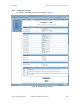
Control Slots
The recommended number of control slots is as stated in Table 44.
Table 44: Control slot settings for all APs in cluster
Number of SMs that
Register to the AP
Number of Control
Slots Recommended
1 to 10 0
11 to 50 1
51 to 150 2
151 to 200 3
Slots reserved for control are used for only SM service requests. For data, the hardware
scheduler uses unreserved slots first, then any unused slots are available with any
reserved slots to the SMs for service requests.
6
See Noting Possible Obstructions in the Fresnel Zone on Page 67.