
User's Manual Part 2

Release8InstallationandConfigurationGuide
Issue2,November2007 Draft5forRegulatoryReview 218
Perform the following procedure to set up the CMMmicro.
IMPORTANT!
Start with the 24-V DC power converter unconnected to AC.
Procedure 17: Setting up a CMMmicro
1. Connect the converter lead whose insulation has a white stripe to +V on the
CMMmicro terminal block.
2. Connect the converter lead whose insulation is solid black to -V on the
CMMmicro terminal block.
3. Connect the power converter to an AC receptacle using the AC power cord.
4. Wait until the green LED labeled RDY flashes.
NOTE: This should occur in less than one minute and will indicate that the
CMMmicro has transitioned from booting to normal operation.
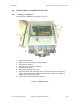
5. Observe which, if any, Ethernet ports are powered, as indicated by a lit red LED
to the right of the Ethernet port.
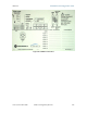
NOTE: The position of this +24-V OUT LED is shown in Figure 68 on Page 219.
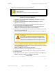
CAUTION!
Never connect any devices other than Cyclone APs and BHs to a
powered port. Powered ports are indicated by a red LED to the right of
the port. (See Item 7 in Figure 69 on Page 220.) A powered port has
24-V DC on Pins 7 and 8 and 24-V return on Pins 4 and 5. This can
damage other networking equipment, such as a computer or a router.
6. On the 8-port Ethernet block of the CMMmicro, use either a straight-through or
crossover Ethernet cable to connect any unpowered port (without the red LED lit)
to a browser-equipped computer.
NOTE: The CMMmicro auto-senses the cable type.
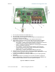
7. Verify these CMMmicro connections against Figure 70 on Page 221.
8. Configure the computer to use DHCP, with no proxy in your network settings.
9. Open the browser.
10. In the address bar, enter 169.254.1.1 (the default IP address of the CMMmicro).
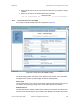
RESULT: The browser displays the CMMmicro Status page.
end of procedure