
User's Manual Part 2

Release8InstallationandConfigurationGuide
Issue2,November2007 Draft5forRegulatoryReview 217
16.5 CONFIGURINGACMMMICROFORTEST
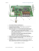
16.5.1 SettingupaCMMmicro
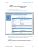
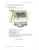
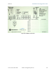
The layout of the CMMmicro is as shown in Figure 67.
1 Weatherized enclosure
2 Thumb-screw/slot-screwdriver door fasteners
3 Punch-out for padlock
4 Ethernet switch and power module
5 Female BNC connector
6 Water-tight bulkhead connectors
7 Flange for attachment (stainless steel so it grounds to tower or building)
using U bolts (provided) or other hardware such as screws or lag bolts or
attachment straps (not provided).
8 Ground strap to ground door to enclosure
Figure 67: CMMmicro layout