
User's Manual Part 2

Release8InstallationandConfigurationGuide
Issue2,November2007 Draft5forRegulatoryReview 200
the alignment drops the power level to −78 dBm and the jitter to 2 or 3, use the refined
alignment, with the following caveats:
◦ When the receiving link is operating at 1X, the Jitter scale is 0 to 15 with desired
jitter between 0 and 4.
◦ When the receiving link is operating at 2X, the Jitter scale is 0 to 15 with desired
jitter between 0 and 9.
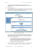
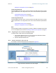
For historical relevance, the General Status tab also shows the RSSI, the unitless
measure of power. Use Power Level and ignore RSSI. RSSI implies more accuracy and
precision than is inherent in its measurement.
NOTE:
Unless the page is set to auto-refresh, the values displayed are from the instant
the General Status tab was selected. To keep a current view of the values,
refresh the browser screen or set to auto-refresh.
Air Delay
This field displays the distance in feet between this SM and the AP. To derive the
distance in meters, multiply the value of this parameter by 0.3048. Distances reported as
less than 200 feet (61 meters) are unreliable.
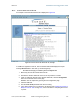
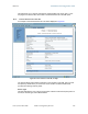
Site Name
This field indicates the name of the physical module. You can assign or change this
name in the SNMP tab of the SM Configuration page. This information is also set into the
sysName SNMP MIB-II object and can be polled by an SNMP management server.
Site Contact
This field indicates contact information for the physical module. You can provide or
change this information in the SNMP tab of the SM Configuration page. This information
is also set into the sysName SNMP MIB-II object and can be polled by an SNMP
management server.
Site Location
This field indicates site information for the physical module. You can provide or change
this information in the SNMP tab of the SM Configuration page.
Maximum Throughput
This field indicates the limit of aggregate throughput for the SM and is based on the
default (factory) limit of the SM and any floating license that is currently assigned to it.