
User's Manual Part 2

Release8InstallationandConfigurationGuide
Issue2,November2007 Draft5forRegulatoryReview 184
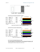
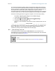
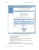
Pin
1 → white / orange ← Pin 1
Pin 2 → white / green ← Pin 2
Pin 3 → white / blue ← Pin 3
Pin 4 → green ← Pin 4
Pin 5 → blue ← Pin 5
Pin 6 → orange ← Pin 6
NOTE:The fourth pair is not
used.
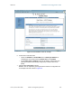
Figure 51: RJ-11 pinout for straight-through sync cable
16.2.11 AlignmentTone—TechnicalDetails
The alignment tone output from a Cyclone module is available on Pin 5 of the RJ-11
connector, and ground is available on Pin 6. Thus the load at the listening device should
be between Pins 5 and 6. The listening device may be a headset, earpiece, or battery-
powered speaker.
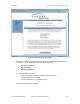
16.3 CONFIGURINGAPOINT‐TO‐MULTIPOINTLINKFORTEST
Perform the following steps to begin the test setup.
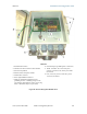
Procedure 5: Setting up the AP for Quick Start
1. In one hand, securely hold the top (larger shell) of the AP. With the other hand,
depress the lever in the back of the base cover (smaller shell). Remove the base
cover.
2. Plug one end of a CAT 5 Ethernet cable into the AP.
3. Plug the Ethernet cable connector labeled To Radio into the jack in the pig tail
that hangs from the power supply.
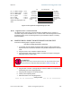
WARNING!
From this point until you remove power from the AP, stay at least as far from the
AP as the minimum separation distance specified in
Table 37 on Page 169.
4. Plug the other connector of the pig tail (this connector labeled To Computer) into
the Ethernet jack of the computing device.
5. Plug the power supply into an electrical outlet.
6. Power up the computing device.
7. Start the browser in the computing device.
end of procedure
1
2
3
4
5
6
1
2
3
4
5
6
sync pulse
serial transmi
t
serial receive
sync pulse
serial receive
serial transmit
override plug
alignment tone
override plug
alignment tone
not
used
not
used
Pin
PinRJ-11 Straight-Thru
Protective Earth (PE)
(ground)
Protective Earth (PE)
(ground)