
User's Manual Part 2

Release8InstallationandConfigurationGuide
Issue2,November2007 Draft5forRegulatoryReview 183
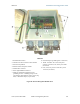
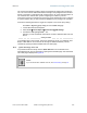
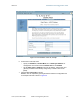
Lock tab ↑ underneath
←
Pin 1
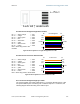
RJ-45 Pinout for Straight-through Ethernet Cable
Pin 1 → white / orange ← Pin 1
Pin 2 → orange ← Pin 2
Pin 3 → white / green ← Pin 3
Pin 4 → blue ← Pin 4
Pin 5 → white / blue ← Pin 5
Pin 6 → green ← Pin 6
Pin 7 → white / brown ← Pin 7
Pin 8 → brown ← Pin 8
Pins 7 and 8 carry power to the
modules.
1
2
3
4
5
6
7
8
1
2
3
4
5
6
7
8
TX+
TX-
RX+
RX-
TX-
TX-
RX+
RX-
+V return
+V
Pin PinRJ-45 Straight-thru
+V return
+V
Figure 49: RJ-45 pinout for straight-through Ethernet cable
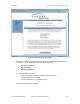
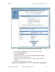
RJ-45 Pinout for Crossover Ethernet Cable
Pin 1 → white / orange ← Pin 3
Pin 2 → orange ← Pin 6
Pin 3 → white / green ← Pin 1
Pin 4 → blue ← Pin 4
Pin 5 → white / blue ← Pin 5
Pin 6 → green ← Pin 2
Pin 7 → white / brown ← Pin 7
Pin 8 → brown ← Pin 8
Pins 7 and 8 carry power to the modules.
7
8
TX+
TX-
RX+
RX-
3
6
1
4
5
2
7
8
RX+
RX-
TX+
TX-
1
2
3
4
5
6
+V
return
+V
+V
+V
return
Pin PinRJ-45 Crossover
Figure 50: RJ-45 pinout for crossover Ethernet cable
RJ-11 Pinout for Straight-through Sync Cable
The Cyclone system uses a utility cable with RJ-11 connectors between the AP or BH
and synchronization pulse. Presuming CAT 5 cable and 6-pin RJ-11 connectors, the
following diagram shows the wiring of the cable for sync.