
User's Manual Part 2


Release8InstallationandConfigurationGuide
Issue2,November2007 Draft5forRegulatoryReview 180
16.2.5 CMM2ComponentLayout
As shown in Figure 125 on Page 344, the CMM2 comprises four assemblies:
• Ethernet switch
• Power transformer
• Interconnect board
• GPS receiver.
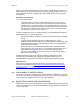
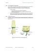
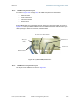
Some CMM2s that were sold earlier had four openings in the bottom plate, as shown in
Figure 47. Currently available CMM2s have two additional Ethernet cable and GPS sync
cable openings to allow use of thicker, shielded cables.
GPS sync
cables
N-connector to GPS antenna
Network feed
Power feed
Ethernet cables
Figure 47: Cyclone CMM2, bottom view
16.2.6 CMMmicroComponentLayout
The layout of the CMMmicro is shown in Figure 48.