
User's Manual Part 2


Release8InstallationandConfigurationGuide
Issue2,November2007 Draft5forRegulatoryReview 179
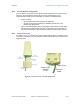
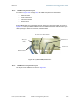
16.2.4 DiagnosticLEDs
The diagnostic LEDs report the following information about the status of the module.
Table 40 and Table 41 identify the LEDs in order of their left-to-right position as the cable
connections face downward.
NOTE:
The LED color helps you distinguish position of the LED. The LED color does
not
indicate any status.
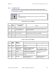
Table 40: LEDs in AP and BHM
Label
Color
when
Active
Status Information
Provided
Notes
LNK/5 green Ethernet link Continuously lit when link is present.
ACT/4 orange
Presence of data activity
on the Ethernet link
Flashes during data transfer. Frequency of flash is not a
diagnostic indication.
GPS/3 red Pulse of sync Continuously lit as pulse as AP receives pulse.
SES/2 green
Unused on the AP
SES is the session indicator on the CMM.
SYN/1 orange Presence of sync Always lit on the AP.
PWR red DC power Always lit when power is correctly supplied.
Table 41: LEDs in SM and BHS
Label
Color
when
Active
Status if
Registered
Notes
Operating Mode Aiming Mode
LNK/5 green Ethernet link
Continuously lit when link is
present.
These five LEDs act as a bar
graph to indicate the relative
quality of alignment. As power
level and jitter improve during
alignment, more of these
LEDs are lit.
ACT/4 orange
Presence of data
activity on the
Ethernet link
Flashes during data transfer.
Frequency of flash is not a
diagnostic indication.
GPS/3 red
Unused
If this module is not registered
to another, then these three
LEDs cycle on and off from left
to right.
SES/2 green
Unused
SYN/1 orange Presence of sync
PWR red DC power
Always lit when power is
correctly supplied.
Always lit when power is
correctly supplied.