
User's Manual Part 2


Release8InstallationandConfigurationGuide
Issue2,November2007 Draft5forRegulatoryReview 173
Grounding Scheme
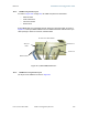
The proper overall antenna grounding scheme per the NEC is illustrated in Figure 128 on
Page 350. In most television antenna or dish installations, a coaxial cable connects the
outdoor electronics with the indoor electronics. To meet NEC 810-20, one typically uses
a coaxial cable feed-through block that connects the outdoor coax to the indoor coax and
also has a screw for attaching a ground wire. This effectively grounds the outer shield of
the coax. The block should be mounted on the outside of the building near the AC main
panel such that the ground wire of the block can be bonded to the primary grounding
electrode system of the structure.
For residential installs, in most cases an outdoor rated unshielded twisted pair (UTP)
cable is sufficient. To comply with the NEC, Last Mile Gear provides the antenna
discharge unit, 300SS or 600SS, for each conductor of the cable. The surge suppressor
must be
◦ positioned
• outside the building.
• as near as practicable to the power service entry panel of the building and
attached to the AC main power ground electrode, or attached to a grounded
water pipe.
5
• far from combustible material.
◦ grounded in accordance with NEC 810-21, with the grounding wire attached to
the screw terminal.
The metal structural elements of the antenna mast also require a separate grounding
conductor. Section 810-15 of the NEC states:
Masts and metal structures supporting antennas shall be grounded in
accordance with Section 810-21.
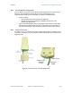
As shown in Figure 128 on Page 350, the Last Mile Gear recommendation for grounding
the metal structural element of the Cyclone mounting bracket (SMMB1) is to route the
grounding wire from the SMMB1 down to the same ground attachment point as is used
for the 300SS discharge unit.
Use 10-AWG (6 mm
2
) Copper Grounding Wire
According to NEC 810-21 3(h), either a 16-AWG copper clad steel wire or a 10-AWG
copper wire may be used. This specification appears to be based on mechanical strength
considerations and not on lightning current handling capabilities.
For example, analysis shows that the two wire types are not equivalent when carrying
a lightning surge that has a 1-microsecond rise by 65-microsecond fall:
◦ The 16-AWG copper clad steel wire has a peak fusing current of 35,000 amps
and can carry 21,000 amps peak, at a temperature just below the ignition point
for paper (454° F or 234° C).
◦ The 10-AWG copper wire has a peak fusing current of 220,000 amps and can
carry 133,000 amps peak, at the same temperature.
5
It is insufficient to merely use the green wire ground in a duplex electrical outlet box for grounding
of the antenna discharge unit.