Release 8 Planning Guide The sync is passed in a cable that connects Pins 1 and 6 of the RJ-11 timing ports of the two modules. When you connect modules in this way, you must also adjust configuration parameters to ensure that ◦ the AP is set to properly receive sync. ◦ the SM will not propagate sync to the AP if the SM itself ceases to receive sync. Perform Procedure 35: Extending network sync on Page 374. 12.8.
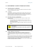
Release 8 Planning Guide Figure 39: Remote AP wired to SM that serves as a relay 12.9 DIAGRAMMING NETWORK LAYOUTS 12.9.1 Accounting for Link Ranges and Data Handling Requirements For aggregate throughput correlation to link distance in both point-to-multipoint and point-to-point links, see 12.9.2 ◦ Link Performance and Encryption Comparisons on Page 61. ◦ all regulations that apply in your region and nation(s). Avoiding Self Interference For 5.2-, 5.4-, and 5.
Release 8 Planning Guide Furthermore, a BH and an AP on the same tower require that the effects of their differing receive start times be mitigated by either ◦ 100 vertical feet (30 meters) or more and as much spectral separation as possible within the same frequency band range. ◦ the use of the frame calculator to tune the Downlink Data % parameter in each, so that the receive start time in each is the same. See Using the Frame Calculator Tool (All) on Page 444.
Release 8 Planning Guide d. click Save Changes. e. click Reboot. end of procedure 12.9.3 Avoiding Other Interference Where signal strength cannot dominate noise levels, the network experiences • bit error corrections. • packet errors and retransmissions. • lower throughput (because bandwidth is consumed by retransmissions) and high latency (due to resends). Be especially cognitive of these symptoms for 900-MHz links.
Release 8 Planning Guide 13 ENGINEERING YOUR IP COMMUNICATIONS 13.1 UNDERSTANDING ADDRESSES A basic understanding of Internet Protocol (IP) address and subnet mask concepts is required for engineering your IP network. 13.1.1 IP Address The IP address is a 32-bit binary number that has four parts (octets). This set of four octets has two segments, depending on the class of IP address. The first segment identifies the network. The second identifies the hosts or devices on the network.
Release 8 13.3 13.3.
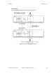
Release 8 Planning Guide NAT Disabled The NAT Disabled implementation is illustrated in Figure 40.
Release 8 Planning Guide NAT with DHCP Client and DHCP Server The NAT with DHCP Client and DHCP Server implementation is illustrated in Figure 41.
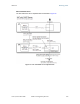
Release 8 Planning Guide NAT with DHCP Client The NAT with DHCP Client implementation is illustrated in Figure 42.
Release 8 Planning Guide NAT with DHCP Server The NAT with DHCP Server implementation is illustrated in Figure 43.
Release 8 Planning Guide NAT without DHCP The NAT without DHCP implementation is illustrated in Figure 44. Figure 44: NAT without DHCP implementation 13.3.2 NAT and VPNs VPN technology provides the benefits of a private network during communication over a public network. One typical use of a VPN is to connect remote employees, who are at home or in a different city, to their corporate network over the public Internet. Any of several VPN implementation schemes is possible.
Release 8 Planning Guide 13.4 DEVELOPING AN IP ADDRESSING SCHEME Cyclone network elements are accessed through IP Version 4 (IPv4) addressing. A proper IP addressing method is critical to the operation and security of a Cyclone network. Each Cyclone module requires an IP address on the network. This IP address is for only management purposes. For security, you should either • assign an unroutable IP address. • assign a routable IP address only if a firewall is present to protect the module.
Release 8 13.4.3 Planning Guide Selecting Non‐routable IP Addresses The factory default assignments for Cyclone network elements are • unique MAC address • IP address of 169.254.1.1, except for an OFDM series BHM, whose IP address is 169.254.1.2 by default • subnet mask of 255.255.0.0 • network gateway address of 169.254.0.0 For each Cyclone radio and CMMmicro, assign an IP address that is both consistent with the IP addressing plan for your network and cannot be accessed from the Internet.
Release 8 Planning Guide 14 ENGINEERING VLANS Cyclone radios support VLAN functionality as defined in the 802.1Q (Virtual LANs) specification, except for the following aspects of that specification: • the following protocols: • Generic Attribute Registration Protocol (GARP) GARV • Spanning Tree Protocol (STP) • Multiple Spanning Tree Protocol (MSTP) • GARP Multicast Registration Protocol (GMRP) • priority encoding (802.1P) before Release 7.0 • embedded source routing (ERIF) in the 802.
Release 8 Planning Guide Table 36: VLAN filters in point-to-multipoint modules then a frame is discarded if… Where VLAN is active, if this parameter value is selected … entering the bridge/ NAT switch through… Ethernet… any combination of VLAN parameter settings TCP/IP… with a VID not in the membership table any combination of VLAN parameter settings because of this VLAN filter in the Cyclone software: Ingress with a VID not in the membership table Local Ingress Allow Frame Types: Tagged Frames O
Release 8 Installation and Configuration Guide INSTALLATION AND CONFIGURATION GUIDE Issue 2, November 2007 Draft 5 for Regulatory Review 167
Release 8 Installation and Configuration Guide 15 AVOIDING HAZARDS Use simple precautions to protect staff and equipment. Hazards include exposure to RF waves, lightning strikes, and power surges. This section specifically recommends actions to abate these hazards. 15.1 EXPOSURE SEPARATION DISTANCES To protect from overexposure to RF energy, install Cyclone radios so as to provide and maintain the minimum separation distances from all persons shown in Table 37.
Release 8 Installation and Configuration Guide P ⋅G S= 4 π d2 where S = power density in W/m2 P = RMS transmit power capability of the radio, in W G = total Tx gain as a factor, converted from dB d = distance from point source, in m d= Rearranging terms to solve for distance yields P⋅G 4π S Table 38 shows calculated minimum separation distances d, recommended distances and resulting power compliance margins for each frequency band and antenna combination.
Release 8 Installation and Configuration Guide Variable Frequency Band Antenna 5.7 GHz d (calculated) Recommended Separation Distance Power Compliance Margin P G S integrated 0.2 W (23 dBm) 5.0 (7 dB) 10 W/m2 9 cm 20 cm (8 in) 5 integrated plus reflector 0.2 W (23 dBm) 316 (25 dB) 10 W/m2 71 cm 1.5 m (5 ft) 4.5 Integrated plus LENS 0.2 W (23 dBm) 50 (17 dB) 1 W/m2 28 cm 50 cm (12 in) 3.
Release 8 Installation and Configuration Guide • 15.2.2 • Install lightning arrestors to transport lightning strikes away from equipment. For example, install a lightning rod on a tower leg other than the leg to which you mount your module. • Connect your lightning rod to ground. • Use a Cyclone 600SS Surge Suppressor on the Ethernet cable where the cable enters any structure. (Instructions for installing a Cyclone 600SS Surge Suppressor are provided in Procedure 28 on Page 349.
Release 8 Installation and Configuration Guide Grounding Scheme The proper overall antenna grounding scheme per the NEC is illustrated in Figure 128 on Page 350. In most television antenna or dish installations, a coaxial cable connects the outdoor electronics with the indoor electronics. To meet NEC 810-20, one typically uses a coaxial cable feed-through block that connects the outdoor coax to the indoor coax and also has a screw for attaching a ground wire.
Release 8 Installation and Configuration Guide Based on the electrical/thermal analysis of these wires, Last Mile Gear recommends 10AWG copper wire for all grounding conductors. Although roughly double the cost of 16AWG copper clad steel wire, 10-AWG copper wire handles six times the surge current from lightning.
Release 8 Installation and Configuration Guide Over time, moisture can cause a cable connector to fail. You can prevent this problem by • using cables that are filled with a dielectric gel or grease. • including a drip loop where the cable approach to the module (typically a CMM2 or CMMmicro) is from above. • wrapping the cable with weather-resistant tape. On a module with an external antenna, use accepted industry practices to wrap the connector to prevent water ingress.
Release 8 Installation and Configuration Guide 16 TESTING THE COMPONENTS The best practice is to connect all components—BHs, APs, GPS antenna, and CMM2 or CMMmicro—in a test setting and initially configure and verify them before deploying them to an installation. In this way, any configuration issues are worked out before going onsite, on a tower, in the weather, where the discovery of configuration issues or marginal hardware is more problematic and work-flow affecting. 16.
Release 8 16.2.2 Installation and Configuration Guide Default Module Configuration From the factory, the Cyclone AP, SM, and BH are all configured to not transmit on any frequency. This configuration ensures that you do not accidentally turn on an unsynchronized module. Site synchronization of modules is required because • • 16.2.3 Cyclone modules • cannot transmit and receive signals at the same time.
Release 8 16.2.4 Installation and Configuration Guide Diagnostic LEDs The diagnostic LEDs report the following information about the status of the module. Table 40 and Table 41 identify the LEDs in order of their left-to-right position as the cable connections face downward. NOTE: The LED color helps you distinguish position of the LED. The LED color does not indicate any status. Table 40: LEDs in AP and BHM Label Color when Active LNK/5 green Ethernet link Continuously lit when link is present.
Release 8 16.2.5 Installation and Configuration Guide CMM2 Component Layout As shown in Figure 125 on Page 344, the CMM2 comprises four assemblies: • Ethernet switch • Power transformer • Interconnect board • GPS receiver. Some CMM2s that were sold earlier had four openings in the bottom plate, as shown in Figure 47. Currently available CMM2s have two additional Ethernet cable and GPS sync cable openings to allow use of thicker, shielded cables.
Release 8 Installation and Configuration Guide LEGEND 1. 2. 3. 4. 5. 6. 7. Weatherized enclosure Thumb-screw/slot-screwdriver door fasteners Punch-out for padlock Ethernet switch and power module Female BNC connector Water-tight bulkhead connectors Flange for attachment (stainless steel for grounding to tower or building) using U bolts (provided) or other hardware such as screws, lag bolts, or attachment straps (not provided) 8. Ground strap (for grounding door to enclosure) 9.
Release 8 16.2.7 Installation and Configuration Guide Standards for Wiring Cyclone modules automatically sense whether the Ethernet cable in a connection is wired as straight-through or crossover. You may use either straight-through or crossover cable to connect a network interface card (NIC), hub, router, or switch to these modules. For a straight-through cable, use the EIA/TIA-568B wire color-code standard on both ends.
Release 8 Installation and Configuration Guide ← Pin 1 Lock tab ↑ underneath RJ-45 Pinout for Straight-through Ethernet Cable Pin 1 → white / orange Pin 2 → orange Pin 3 → white / green Pin 4 → blue Pin 5 → white / blue Pin 6 → green Pin 7 → white / brown Pin 8 → brown Pins 7 and 8 carry power to the modules.
Release 8 Installation and Configuration Guide Pin RJ-11 Straight-Thru sync pulse 1 → white / orange ← Pin 1 → white / green ← Pin 2 → white / blue ← Pin 3 → green ← Pin 4 → blue ← Pin 5 → orange ← Pin 6 NOTE: The fourth pair is not used.
Release 8 Installation and Configuration Guide The Cyclone AP interface provides a series of web pages to configure and monitor the unit. You can access the web-based interface through a computing device that is either directly connected or connected through a network to the AP.
Release 8 Installation and Configuration Guide Figure 52: Quick Start tab of AP, example Quick Start is a wizard that helps you to perform a basic configuration that places an AP into service. Only the following parameters must be configured: • RF Carrier Frequency • Synchronization • Network IP Address In each Quick Start tab, you can • specify the settings to satisfy the requirements of the network. • review the configuration selected. • save the configuration to non-volatile memory.
Release 8 Installation and Configuration Guide Procedure 7: Using Quick Start to configure a standalone AP for test 1. At the bottom of the Quick Start tab, click the Go To Next Page => button. RESULT: The AP responds by opening the RF Carrier Frequency tab. An example of this tab is shown in Figure 53. Figure 53: Radio Frequency Carrier tab of AP, example 2. From the pull-down menu in the lower left corner of this tab, select a frequency for the test. 3. Click the Go To Next Page => button.
Release 8 Installation and Configuration Guide Figure 54: Synchronization tab of AP, example 4. At the bottom of this tab, select Generate Sync Signal. 5. Click the Go To Next Page => button. RESULT: The AP responds by opening the LAN IP Address tab. An example of this tab is shown in Figure 55.
Release 8 Installation and Configuration Guide Figure 55: LAN IP Address tab of AP, example 6. At the bottom of this tab, either • specify an IP Address, a Subnet Mask, and a Gateway IP Address for management of the AP and leave the DHCP state set to Disabled. • set the DHCP state to Enabled to have the IP address, subnet mask, and gateway IP address automatically configured by a domain name server (DNS). 7. Click the Go To Next Page => button.
Release 8 Installation and Configuration Guide Figure 56: Review and Save Configuration tab of AP, example 8. Ensure that the initial parameters for the AP are set as you intended. 9. Click the Save Changes button. 10. Click the Reboot button. RESULT: The AP responds with the message Reboot Has Been Initiated… 11. Wait until the indicator LEDs are not red. 12. Trigger your browser to refresh the page until the AP redisplays the General Status tab. 13. Wait until the red indicator LEDs are not lit.
Release 8 Installation and Configuration Guide Cyclone encourages you to experiment with the interface. Unless you save a configuration and reboot the AP after you save the configuration, none of the changes are effected. 16.3.2 Time Tab of the AP To proceed with the test setup, click the Configuration link on the left side of the General Status tab. When the AP responds by opening the Configuration page to the General tab, click the Time tab. An example of this tab is displayed in Figure 57.
Release 8 Installation and Configuration Guide obtain time and date before the first (or next) 15-minute interval query of the NTP server, click Get Time through NTP.
Release 8 16.3.3 Installation and Configuration Guide Session Status Tab of the AP An example of the AP Session Status tab is displayed in Figure 58. Figure 58: Session Status tab data from AP, example If no SMs are registered to this AP, then the Session Status tab displays the simple message No sessions. In this case, try the following steps. Procedure 9: Retrying to establish a point-to-multipoint link 1. More finely aim the SM or SMs toward the AP. 2.
Release 8 Installation and Configuration Guide 7. On the left side of the SM Home page, click the Configuration button. RESULT: The Configuration page of the SM opens. 8. Click the Radio tab. 9. If the transmit frequency of the AP is not selected in the Custom Radio Frequency Scan Selection List parameter, select the frequency that matches. 10. If the Color Code parameter on this page is not identical to the Color Code parameter you noted from the AP, change one of them so that they match. 11.
Release 8 Installation and Configuration Guide Site Name This field indicates the name of the SM. You can assign or change this name on the Configuration web page of the SM. This information is also set into the sysName SNMP MIB-II object and can be polled by an SNMP management server. Software Version This field displays the software release that operates on the SM, the release date and time of the software. Software Boot Version This field indicates the CYCLONEBOOT version number.
Release 8 Installation and Configuration Guide the alignment drops the power level to −78 dBm and the jitter to 2 or 3, use the refined alignment, with the following caveats: ◦ When the receiving link is operating at 1X, the Jitter scale is 0 to 15 with desired jitter between 0 and 4. ◦ When the receiving link is operating at 2X, the Jitter scale is 0 to 15 with desired jitter between 0 and 9. The Session Status tab also shows a historical RSSI, a unitless measure of power.
Release 8 Installation and Configuration Guide ◦ Setting the Configuration Source on Page 295. Low Priority Uplink CIR This field displays the value that is currently in effect for the SM, with the source of that value in parentheses. The configuration source of the value is indicated in parentheses. See ◦ Committed Information Rate on Page 86 ◦ Setting the Configuration Source on Page 295.
Release 8 Installation and Configuration Guide This tab allows you to view the web pages of registered SMs over the RF link. To view the pages for a selected SM, click its link. The General Status tab of the SM opens. 16.3.6 General Status Tab of the SM An example of the General Status tab of an SM is displayed in Figure 60. Figure 60: General Status tab of SM, example The General Status tab provides information on the operation of this SM.
Release 8 Installation and Configuration Guide Software Version This field indicates the Cyclone system release, the time and date of the release, and whether communications involving the module are secured by DES or AES encryption (see Encrypting Cyclone Radio Transmissions on Page 375). If you request technical support, provide the information from this field. Software BOOT Version This field indicates the version of the CYCLONEBOOT file.
Release 8 Installation and Configuration Guide the alignment drops the power level to −78 dBm and the jitter to 2 or 3, use the refined alignment, with the following caveats: ◦ When the receiving link is operating at 1X, the Jitter scale is 0 to 15 with desired jitter between 0 and 4. ◦ When the receiving link is operating at 2X, the Jitter scale is 0 to 15 with desired jitter between 0 and 9. For historical relevance, the General Status tab also shows the RSSI, the unitless measure of power.
Release 8 16.3.7 Installation and Configuration Guide Continuing the Test of Point‐to‐Multipoint Links To resume the test of links, perform the following steps. Procedure 10: Verifying and recording information from SMs 1. Verify that the Session Status field of the General Status tab in the SM indicates REGISTERED. 2.
Release 8 16.3.8 Installation and Configuration Guide General Status Tab of the AP An example of an AP General Status tab is displayed in Figure 61. Figure 61: General Status tab of AP, example The General Status tab provides information on the operation of this AP. This is the tab that opens by default when you access the GUI of the AP. The General Status tab provides the following read-only fields. Device Type This field indicates the type of the Cyclone module.
Release 8 Installation and Configuration Guide Board Type This field indicates the series of hardware. See Designations for Hardware in Radios on Page 372. FPGA Version This field indicates the version of the field-programmable gate array (FPGA) on the module. When you request technical support, provide the information from this field. Uptime This field indicates how long the module has operated since power was applied. System Time This field provides the current time.
Release 8 Installation and Configuration Guide Site Contact This field indicates contact information for the physical module. You can provide or change this information in the SNMP tab of the AP Configuration page. This information is also set into the sysName SNMP MIB-II object and can be polled by an SNMP management server. Site Location This field indicates site information for the physical module. You can provide or change this information in the SNMP tab of the AP Configuration page.
Release 8 Installation and Configuration Guide Procedure 12: Setting up the BH for Quick Start 1. In one hand, securely hold the top (larger shell) of the BH that you intend to deploy as a timing master. With the other hand, depress the lever in the back of the base cover (smaller shell). Remove the base cover. 2. Plug one end of a CAT 5 Ethernet cable into the timing master. 3. Plug the other end of the Ethernet cable into the jack in the pig tail that hangs from the power supply. 4.
Release 8 Installation and Configuration Guide Figure 62: Quick Start tab of BHM, example Quick Start is a wizard that helps you to perform a basic configuration that places a BHM into service. Only the following variables must be configured: • RF Carrier Frequency • Synchronization • Network IP Address In each page under Quick Start, you can • specify the settings to satisfy the requirements of the network. • review the configuration selected. • save the configuration to non-volatile memory.
Release 8 Installation and Configuration Guide Procedure 13: Using Quick Start to configure the BHs for test 1. At the bottom of the Quick Start tab, click the Go To Next Page => button. RESULT: The BHM responds by opening the RF Carrier Frequency tab. 2. From the pull-down menu in the lower left corner of this page, select a frequency for the test. 3. Click the Go To Next Page => button. RESULT: The BHM responds by opening the Synchronization tab. 4.
Release 8 Installation and Configuration Guide Figure 63: Time tab of BHM, example To have each log in the BHM correlated to a meaningful time and date, either a reliable network element must pass time and date to the BHM or you must set the time and date whenever a power cycle of the BHM has occurred. A network element passes time and date in any of the following scenarios: • A connected CMM2 passes time and date (GPS time and date, if received).
Release 8 Installation and Configuration Guide If you enter a time and date, the format for entry is Time : hh / mm / ss Date : MM / dd / yyyy where hh mm ss MM dd yyyy represents the two-digit hour in the range 00 to 24 represents the two-digit minute represents the two-digit second represents the two-digit month represents the two-digit day represents the four-digit year Proceed with the test setup as follows. Procedure 14: Setting up the BHS for test 1.
Release 8 Installation and Configuration Guide Figure 64: Remote Subscribers tab of BHM, example Issue 2, November 2007 Draft 5 for Regulatory Review 210
Release 8 16.4.3 Installation and Configuration Guide Beginning the Test of Point‐to‐Point Links To begin the test of your BH link, in the Remote Subscribers tab of the BHM, click the link to the BHS. The BHS GUI opens to the General Status tab of its Home page. An example of the BHS General Status tab is displayed in Figure 65. Figure 65: General Status tab of BHS, example The General Status tab provides information on the operation of this BHS.
Release 8 Installation and Configuration Guide Software BOOT Version This field indicates the version of the CYCLONEBOOT file. If you request technical support, provide the information from this field. Board Type This field indicates the series of hardware. See Designations for Hardware in Radios on Page 372. FPGA Version This field indicates the version of the field-programmable gate array (FPGA) on the module. When you request technical support, provide the information from this field.
Release 8 Installation and Configuration Guide ◦ When the receiving link is operating at 2X, the Jitter scale is 0 to 15 with desired jitter between 0 and 9. For historical relevance, the General Status tab also shows the RSSI, the unitless measure of power. Use Power Level and ignore RSSI. RSSI implies more accuracy and precision than is inherent in its measurement. NOTE: Unless the page is set to auto-refresh, the values displayed are from the instant the General Status tab was selected.
Release 8 Installation and Configuration Guide 3. Systematically ensure that you can retrieve this data when you prepare to deploy the BHS. 4. Return your browser to the General Status tab of the BHM. end of procedure 16.4.5 General Status Tab of the BHM An example of a BHM General Status tab is displayed in Figure 66. Figure 66: General Status tab of BHM, example The Status page provides information on the operation of the module. This is the default web page for the module.
Release 8 Installation and Configuration Guide is secured by DES or AES encryption (see Encrypting Cyclone Radio Transmissions on Page 375). When you request technical support, provide the information from this field. Software BOOT Version This field indicates the version of the CYCLONEBOOT file. If you request technical support, provide the information from this field. Board Type This field indicates the series of hardware. See Designations for Hardware in Radios on Page 372.
Release 8 Installation and Configuration Guide Site Name This field indicates the name of the physical module. You can assign or change this name in the SNMP tab of the BHM Configuration page. This information is also set into the sysName SNMP MIB-II object and can be polled by an SNMP management server. Site Contact This field indicates contact information for the physical module. You can provide or change this information in the SNMP tab of the BHM Configuration page.
Release 8 Installation and Configuration Guide 16.5 CONFIGURING A CMMMICRO FOR TEST 16.5.1 Setting up a CMMmicro The layout of the CMMmicro is as shown in Figure 67.
Release 8 Installation and Configuration Guide Perform the following procedure to set up the CMMmicro. IMPORTANT! Start with the 24-V DC power converter unconnected to AC. Procedure 17: Setting up a CMMmicro 1. Connect the converter lead whose insulation has a white stripe to +V on the CMMmicro terminal block. 2. Connect the converter lead whose insulation is solid black to -V on the CMMmicro terminal block. 3. Connect the power converter to an AC receptacle using the AC power cord. 4.
Release 8 Installation and Configuration Guide Figure 68: CMMmicro door label Issue 2, November 2007 Draft 5 for Regulatory Review 219
Release 8 Installation and Configuration Guide 1 2 3 24 V DC power connection on terminal block (+V). 24 V DC ground connection on terminal block (-V). Ground bonding point for CMMmicro. Ground connection on terminal block, for grounding to Protective Earth (PE) . Female BNC connector for connecting to coax cable from GPS antenna. Status display of eight green LEDs.
Release 8 Installation and Configuration Guide Figure 70: CMMmicro connections Issue 2, November 2007 Draft 5 for Regulatory Review 221
Release 8 16.5.2 Installation and Configuration Guide Status Page of the CMMmicro An example of a CMMmicro Status page is displayed in Figure 71. Figure 71: Status page of CMMmicro, example The Status page provides information on the operation of this CMMmicro. This is the default web page for the CMMmicro. The Status page provides the following fields. Link A red dot indicates that the port is active and detects Ethernet traffic.
Release 8 Installation and Configuration Guide Powered A red dot indicates that the port is powered with 24 V DC to provide power to an AP or BH. A grey dot indicates that the port is not powered. Port power is turned on and off in the Port Power Control parameter of the Configuration page. A CMMmicro comes from the factory with no Ethernet ports powered. CAUTION! Never connect any devices other than Cyclone APs and BHs to a powered port. Powered ports are indicated by a red LED to the right of the port.
Release 8 Installation and Configuration Guide Height If the CMMmicro receives the signal from a GPS antenna, then this field displays the elevation (above sea level) of the GPS antenna. Uptime This field displays how much time has elapsed since the last boot of the CMMmicro. Satellites Tracked This field displays how many satellites the CMMmicro is tracking. Longitude If the CMMmicro receives the signal from a GPS antenna, then this field displays the longitude of the site.
Release 8 16.5.3 Installation and Configuration Guide Configuration Page of the CMMmicro An example of the CMMmicro Configuration page is displayed in Figure 72.
Release 8 Installation and Configuration Guide The Configuration web page contains all of the configurable parameters that define how the CMMmicro operates. The first line of information on the Configuration screen echoes the Device Type from the Status web page.
Release 8 Installation and Configuration Guide Lan1 IP Enter the IP address to be associated with the Ethernet connection on this CMMmicro. The default address is 169.254.1.1. If you set and then forget this parameter, then you must both 1. physically access the module. 2. use the CMMmicro override toggle switch to electronically access the module configuration parameters at 169.254.1.1. See Overriding Forgotten IP Addresses or Passwords on CMMmicro on Page 381.
Release 8 Installation and Configuration Guide Power Port Control Ensure that power is off for every port that connects to a router, computer, or other network equipment. Turn on 24-V DC power for ports that connect to Cyclone APs or BHs. CAUTION! Never connect any devices other than Cyclone APs and BHs to a powered port. Powered ports are indicated by a red LED to the right of the port. (See Item 7 in Figure 69 on Page 220.) A powered port has 24-V DC on Pins 7 and 8 and 24-V return on Pins 4 and 5.
Release 8 Installation and Configuration Guide NOTE: You can unset either password (revert the access to no password required). To do so, type a space into the field and reboot the module. You must enter any password twice to allow the system to verify that the password is not mistyped. After any password is set and a reboot of the module has occurred, a Password Set indicator appears to the right of the field. RECOMMENDATION: Note the passwords that you enter.
Release 8 Installation and Configuration Guide RECOMMENDATION: For more information on CIDR, execute an Internet search on “Classless Interdomain Routing.” The default treatment is to allow all networks access. Trap Address Specify the IP address (xxx.xxx.xxx.xxx) of one to ten servers (Prizm or NMS) to which trap information should be sent. Trap information informs the monitoring systems that something has occurred. For example, trap information is sent • after a reboot of the module.
Release 8 Installation and Configuration Guide VLAN Port Configuration Each column in the VLAN Port Configuration section of Figure 72 corresponds to a port. Checkboxes in each column control which ports can transmit traffic that arrives on the (column) port. For example, in the first column if only Port 2 is checked, then Port 1 (column 1) will only be allowed to send data out on Port 2 (checked box). Port 2 (second column) is able to send data out on all other ports.
Release 8 Installation and Configuration Guide In addition, when you click Reboot, the following events occur and are logged: 16.5.4 • The CMMmicro reboots. • Any AP or BH that receives power from the CMMmicro loses power and thus also reboots. • Any AP or BH that does not receive power but receives sync from the CMMmicro loses and then regains sync. Configuring Modules for Connection to CMMmicro After configuring the CMMmicro, configure the APs and BHs as follows.
Release 8 Installation and Configuration Guide The GPS Status page provides information from the GPS antenna and information about the GPS receiver in the CMMmicro. Antenna Connection This field displays the status of the signal from the antenna as follows: • OK indicates that the GPS interface board is detecting an incoming signal on the coaxial cable from the GPS antenna. • No Antenna indicates the GPS interface board is not detecting any incoming signal.
Release 8 Installation and Configuration Guide Ports 1 through 8 are the regular ports, connected to APs, BHs, or other network elements. Port 9 is the connection between the managed switch and the CMMmicro processor. Thus, updates to interface pages, SNMP activities, and FTP and telnet sessions create traffic on Port 9. These Ethernet statistics can also be retrieved from the CMMmicro by a Network Management Station using SNMP.
Release 8 Installation and Configuration Guide 17 PREPARING COMPONENTS FOR DEPLOYMENT Your test of the modules not only verified that they are functional, but also yielded data that you have stored about them. Most efficiently preparing modules for deployment involves • retrieving that data. • systematically collecting the data into a single repository, while keeping a strong (quick) association between the data and the module.
Release 8 Installation and Configuration Guide 18 CONFIGURING FOR THE DESTINATION 18.1 CONFIGURING AN AP FOR THE DESTINATION If an ADMINISTRATOR-level password has been set in the AP, you must log into the module before you can configure its parameters. See Managing Module Access by Passwords on Page 377. 18.1.1 General Tab of the AP An example of an AP General tab is displayed in Figure 75.
Release 8 Installation and Configuration Guide Figure 75: General tab of AP, example The General tab of the AP contains many of the configurable parameters that define how the AP and the SMs in the sector operate. As shown in Figure 75, you may set the Configuration page parameters as follows.
Release 8 Installation and Configuration Guide Device Setting You can temporarily transform an AP into an SM and thereby use the spectrum analyzer functionality. See Using the AP as a Spectrum Analyzer on Page 370. Otherwise, the selection for this parameter is AP. Link Speeds Specify the type of link speed for the Ethernet connection. The default for this parameter is that all speeds are selected. The recommended setting is a single speed selection for all APs, BHs, and SMs in the operator network.
Release 8 Installation and Configuration Guide CAUTION! An inappropriately low Bridge Entry Timeout setting may lead to temporary loss of communication with some end users. Translation Bridging If you want the Translation Bridging feature, select Enabled. This has numerous implications. For a full description of them, see Uplink Frame Contents on Page 81.
Release 8 Installation and Configuration Guide Save Changes When you click this button, any changes that you made on the this tab are recorded in flash memory. However, these changes do not apply until the next reboot of the module. Reboot When you click this button 1. the module reboots. 2. any changes that you saved by a click of the Save Changes button are implemented. 18.1.2 IP Tab of the AP An example of the IP tab of the AP is displayed in Figure 76.
Release 8 Installation and Configuration Guide You may set the IP tab parameters as follows. LAN1 Network Interface Configuration, IP Address Enter the non-routable IP address to associate with the Ethernet connection on this AP. (The default IP address from the factory is 169.254.1.1.) If you set and then forget this parameter, then you must both 1. physically access the module. 2. use an override plug to electronically access the module configuration parameters at 169.254.1.1.
Release 8 Installation and Configuration Guide NOTE: Where space is limited for subnet allocation, be advised that an SM need not have an operator-assigned IP address. The SM is directly accessible without an LUID if either the SM Color Code parameter is set to 0 or the AP has a direct Ethernet connection to the SM. The IP Configuration page also provides the following buttons. Save Changes When you click this button, any changes that you made on this tab are recorded in flash memory.
Release 8 Installation and Configuration Guide The Radio tab of the AP contains some of the configurable parameters that define how the AP operates. As shown in Figure 77, you may set the Radio tab parameters as follows. Radio Frequency Carrier Specify the frequency for the module to transmit. The default for this parameter is None. (The selection labeled Factory requires a special software key file for implementation.
Release 8 Installation and Configuration Guide AP or SM, the greater value allows you to attempt greater distance where the RF environment and Fresnel zone6 are especially clear. A value of 15 for this parameter decreases the number of available data slots by 1. With a higher value, the number is further decreased as the AP compensates for the expected additional air delay.
Release 8 Installation and Configuration Guide If too few reserved control slots are specified, then latency increases in high traffic periods. If too many are specified, then the maximum capacity is unnecessarily reduced. External Filters Delay This parameter is present in only 900-MHz modules and can have effect in only those that have interference mitigation filter(s). Leave this value set to 0, regardless of whether the AP has an interference mitigation filter.
Release 8 Installation and Configuration Guide • confirm that the power setting is compliant following any reset of the module to factory defaults. For information on how to calculate the permissible transmitter output power to enter in this parameter, see Adjusting Transmitter Output Power on Page 330. The Radio tab also provides the following buttons. Save Changes When you click this button, any changes that you made on this tab are recorded in flash memory.
Release 8 18.1.4 Installation and Configuration Guide SNMP Tab of the AP An example of the SNMP tab of the AP is displayed in Figure 78.
Release 8 Installation and Configuration Guide You may set the SNMP tab parameters as follows. Community String Specify a control string that allows an Network Management Station (NMS) to access SNMP information. No spaces are allowed in this string. The default string is Cyclone. The Community String value is clear text and is readable by a packet monitor. Additional security derives from the configuration of the Accessing Subnet, Trap Address, and Permission parameters.
Release 8 Installation and Configuration Guide Site Name Specify a string to associate with the physical module. This parameter is written into the sysName SNMP MIB-II object and can be polled by PrizmEMS or an NMS. The buffer size for this field is 128 characters. Site Contact Enter contact information for the module administrator. This parameter is written into the sysContact SNMP MIB-II object and can be polled by PrizmEMS or an NMS. The buffer size for this field is 128 characters.
Release 8 18.1.5 Installation and Configuration Guide Quality of Service (QoS) Tab of the AP An example of the Quality of Service (QoS) tab of the AP is displayed in Figure 79. Figure 79: Quality of Service (QoS) tab of AP, example In the Quality of Service (QoS) tab, you may set AP bandwidth parameters as follows. Sustained Uplink Data Rate Specify the rate that each SM registered to this AP is replenished with credits for transmission. This default imposes no restriction on the uplink.
Release 8 Installation and Configuration Guide Sustained Downlink Data Rate Specify the rate at which the AP should be replenished with credits (tokens) for transmission to each of the SMs in its sector. This default imposes no restriction on the uplink. See ◦ Maximum Information Rate (MIR) Parameters on Page 84 ◦ Interaction of Burst Allocation and Sustained Data Rate Settings on Page 86 ◦ Setting the Configuration Source on Page 295.
Release 8 18.1.6 Installation and Configuration Guide Security Tab of the AP An example of the Security tab of the AP is displayed in Figure 80. Figure 80: Security tab of AP, example In the Security tab of the AP, you may set the following parameters.
Release 8 Installation and Configuration Guide Authentication Mode If the AP has authentication capability, then you can use this field to select from among the following authentication modes: • Authentication Disabled—the AP requires no SMs to authenticate. • Authentication Required—the AP requires any SM that attempts registration to be authenticated in BAM or Prizm before registration. If the AP does not have authentication capability, then this parameter displays Authentication Not Available.
Release 8 Installation and Configuration Guide Allowed Source IP 1 to 3 If you selected IP Access Filtering Enabled for the IP Access Control parameter, then you must populate at least one of the three Allowed Source IP parameters or have no access permitted to the AP from any IP address. You may populate as many as all three. If you selected IP Access Filtering Disabled for the IP Access Control parameter, then no entries in this parameter are read, and access from all IP addresses is permitted.
Release 8 18.1.7 Installation and Configuration Guide VLAN Tab of the AP An example of the AP VLAN tab is displayed in Figure 81. Figure 81: VLAN tab of AP, example In the VLAN tab of the AP, you may set the following parameters. VLAN Specify whether VLAN functionality for the AP and all linked SMs should (Enabled) or should not (Disabled) be allowed. The default value is Disabled.
Release 8 Installation and Configuration Guide VLAN Aging Timeout Specify how long the AP should keep dynamically learned VIDs. The range of values is 5 to 1440 (minutes). The default value is 25 (minutes). NOTE: VIDs that you enter for the Management VID and VLAN Membership parameters do not time out. Management VID Enter the VID that the operator wishes to use to communicate with the module manager. The range of values is 1 to 4095. The default value is 1.
Release 8 18.1.8 Installation and Configuration Guide VLAN Membership Tab of the AP An example of the VLAN Membership tab of the AP is displayed in Figure 82. Figure 82: VLAN Membership tab of AP, example You may set the VLAN Membership tab parameter as follows. VLAN Membership Table Configuration For each VLAN in which you want the AP to be a member, enter the VLAN ID and then click the Add Member button.
Release 8 18.1.9 Installation and Configuration Guide DiffServe Tab of the AP An example of the DiffServe tab of the AP is displayed in Figure 83.
Release 8 Installation and Configuration Guide You may set the following DiffServe tab parameters. CodePoint 1 through CodePoint 47 The default priority value for each settable CodePoint is shown in Figure 113. Priorities of 0 through 3 map to the low-priority channel; 4 through 7 to the high-priority channel. The mappings are the same as 802.1p VLAN priorities. Consistent with RFC 2474 CodePoint 0 is predefined to a fixed priority value of 0 (low-priority channel).
Release 8 Installation and Configuration Guide 18.1.10 Unit Settings Tab of the AP An example of the Unit Settings tab of the AP is shown in Figure 84. Figure 84: Unit Settings tab of AP, example The Unit Settings tab of the AP contains an option for how the AP should react when it detects a connected override plug. You may set this option as follows. Set to Factory Defaults Upon Default Plug Detection If Enabled is checked, then an override/default plug functions as a default plug.
Release 8 Installation and Configuration Guide Save Changes When you click this button, any changes that you made on all tabs are recorded in flash memory. However, these changes do not apply until the next reboot of the module. Reboot When you click this button 1. the module reboots. 2. any changes that you saved by a click of the Save Changes button are implemented.
Release 8 18.2.1 Installation and Configuration Guide General Tab of the SM An example of a General tab in the SM is displayed in Figure 85. Figure 85: General tab of SM, example In the General tab of the SM, you may set the following parameters. Link Speeds Specify the type of link speed for the Ethernet connection. The default for this parameter is that all speeds are selected. The recommended setting is a single speed selection for all APs, BHs, and SMs in the operator network.
Release 8 Installation and Configuration Guide 802.3 Link Enable/Disable Specify whether to enable or disable Ethernet/802.3 connectivity on the wired port of the SM. This parameter has no effect on the wireless link. When you select Enable, this feature allows traffic on the Ethernet/802.3 port. This is the factory default state of the port. When you select Disable, this feature prevents traffic on the port.
Release 8 Installation and Configuration Guide Frame Timing Pulse Gated If this SM extends the sync pulse to a BH master or an AP, select either • Enable—If this SM loses sync from the AP, then do not propagate a sync pulse to the BH timing master or other AP. This setting prevents interference in the event that the SM loses sync. • Disable—If this SM loses sync from the AP, then propagate the sync pulse to the BH timing master or other AP. See Wiring to Extend Network Sync on Page 374.
Release 8 Installation and Configuration Guide Figure 86: NAT tab of SM with NAT disabled, example This implementation is illustrated in Figure 40 on Page 157. In the NAT tab of an SM with NAT disabled, you may set the following parameters.
Release 8 Installation and Configuration Guide NAT Enable/Disable This parameter enables or disabled the Network Address Translation (NAT) feature for the SM. NAT isolates devices connected to the Ethernet/wired side of an SM from being seen directly from the wireless side of the SM.
Release 8 Installation and Configuration Guide Radio Public Network Interface Configuration, DHCP State This parameter is not configurable when NAT is disabled. ARP Cache Timeout If a router upstream has an ARP cache of longer duration (as some use 30 minutes), enter a value of longer duration than the router ARP cache. The default value of this field is 20 minutes.
Release 8 Installation and Configuration Guide Figure 87: IP tab of SM with NAT disabled, example This implementation is illustrated in Figure 40 on Page 157. In the IP tab of an SM with NAT disabled, you may set the following parameters. LAN1 Network Interface Configuration, IP Address Enter the non-routable IP address to associate with the Ethernet connection on this SM. (The default IP address from the factory is 169.254.1.1.) If you set and then forget this parameter, then you must both 1.
Release 8 Installation and Configuration Guide LAN1 Network Interface Configuration, Network Accessibility Specify whether the IP address of the SM should be visible to only a device connected to the SM by Ethernet (Local) or should be visible to the AP as well (Public). LAN1 Network Interface Configuration, Subnet Mask Enter an appropriate subnet mask for the SM to communicate on the network. The default subnet mask is 255.255.0.0. See Allocating Subnets on Page 162.
Release 8 18.2.3 Installation and Configuration Guide NAT and IP Tabs of the SM with NAT Enabled An example of the NAT tab in an SM with NAT enabled is displayed in Figure 88. Figure 88: NAT tab of SM with NAT enabled, example In the NAT tab of an SM with NAT enabled, you may set the following parameters.
Release 8 Installation and Configuration Guide NAT Enable/Disable This parameter enables or disabled the Network Address Translation (NAT) feature for the SM. NAT isolates devices connected to the Ethernet/wired side of an SM from being seen directly from the wireless side of the SM.
Release 8 Installation and Configuration Guide Radio Public Network Interface Configuration, IP Address If DHCP Client is enabled, then the DHCP server automatically assigns this address. Otherwise, assign the IP address for over-the-air management of the SM when the radio public interface is enabled in the next parameter. Radio Public Network Interface Configuration, Interface Enable/Disable If you want over-the-air management capability for the SM, select Enabled.
Release 8 Installation and Configuration Guide DHCP Client Enable/Disable Select either • Enabled to allow the network DHCP server to assign IP addresses, subnet masks, and gateway IP addresses to devices that are attached to the SM. • Disabled to • disable DHCP server assignment of this address. • enable the operator to assign this address. The implementation of NAT with DHCP client is illustrated in Figure 42 on Page 159.
Release 8 Installation and Configuration Guide Save Changes When you click this button, any changes that you made on all tabs are recorded in flash memory. However, these changes do not apply until the next reboot of the module. Reboot When you click this button 1. the module reboots. 2. any changes that you saved by a click of the Save Changes button are implemented. An example of the IP tab in an SM with NAT enabled is displayed in Figure 89.
Release 8 Installation and Configuration Guide Reboot When you click this button 1. the module reboots. 2. any changes that you saved by a click of the Save Changes button are implemented. An example of the IP tab in an SM with NAT enabled is displayed in Figure 89. 18.2.4 Radio Tab of the SM An example of the Radio tab in the SM is displayed in Figure 90. Figure 90: Radio tab of SM, example In the Radio tab of the SM, you may set the following parameters.
Release 8 Installation and Configuration Guide IMPORTANT! In the 2.4-GHz frequency band, the SM can register to an AP that transmits on a frequency 2.5 MHz higher than the frequency that the SM receiver locks when the scan terminates as successful. This establishes a poor-quality link. To prevent this, select frequencies that are at least 5 MHz apart. In a 2.4-GHz SM, this parameter displays all available channels, but has only three recommended channels selected by default. See 2.
Release 8 Installation and Configuration Guide Transmitter Output Power Nations and regions may regulate transmitter output power. For example ◦ Both 900-MHz and 5.7-GHz modules are available as connectorized radios, which require the operator to adjust power to ensure regulatory compliance. In addition to setting the power in the 5.7-GHz connectorized module, the operator must set the antenna gain/cable loss such that the module can accurately report received power at the antenna.
Release 8 18.2.5 Installation and Configuration Guide SNMP Tab of the SM An example of the SNMP tab in an SM is displayed in Figure 91. Figure 91: SNMP tab of SM, example In the SNMP tab of the SM, you may set the following parameters. Community String Specify a control string that allows Prizm or an NMS (Network Management Station) to access MIB information about this SM. No spaces are allowed in this string. The default string is Cyclone.
Release 8 Installation and Configuration Guide The Community String value is clear text and is readable by a packet monitor. Additional security derives from the configuration of the Accessing Subnet, Trap Address, and Permission parameters. Accessing Subnet Specify the addresses that are allowed to send SNMP requests to this SM. Prizm or the NMS has an address that is among these addresses (this subnet). You must enter both • The network IP address in the form xxx.xxx.xxx.
Release 8 Installation and Configuration Guide Site Contact Enter contact information for the module administrator. This parameter is written into the sysContact SNMP MIB-II object and can be polled by Prizm or an NMS. The buffer size for this field is 128 characters. Site Location Enter information about the physical location of the module. This parameter is written into the sysLocation SNMP MIB-II object and can be polled by Prizm or an NMS. The buffer size for this field is 128 characters.
Release 8 18.2.6 Installation and Configuration Guide Quality of Service (QoS) Tab of the SM An example of the Quality of Service (QoS) tab in the SM is displayed in Figure 92. Figure 92: Quality of Service (QoS) tab of SM, example In the Quality of Service (QoS) tab of the SM, you may set the following parameters. Sustained Uplink Data Rate Specify the rate that this SM is replenished with credits for transmission. This default imposes no restriction on the uplink.
Release 8 Installation and Configuration Guide Uplink Burst Allocation Specify the maximum amount of data to allow this SM to transmit before being recharged at the Sustained Uplink Data Rate with credits to transmit more. See ◦ Maximum Information Rate (MIR) Parameters on Page 84 ◦ Interaction of Burst Allocation and Sustained Data Rate Settings on Page 86 ◦ Setting the Configuration Source on Page 295.
Release 8 Installation and Configuration Guide Hi Priority Downlink CIR See ◦ High-priority Bandwidth on Page 86 ◦ Committed Information Rate on Page 86 ◦ Setting the Configuration Source on Page 295. The Quality of Service (QoS) tab also provides the following buttons. Save Changes When you click this button, any changes that you made in this tab are recorded in flash memory. However, these changes do not apply until the next reboot of the module. Reboot When you click this button 1.
Release 8 18.2.7 Installation and Configuration Guide Security Tab of the SM An example of the Security tab in an SM is displayed in Figure 93.
Release 8 Installation and Configuration Guide In the Security tab of the SM, you may set the following parameters. Authentication Key Only if the AP to which this SM will register requires authentication, specify the key that the SM should use when authenticating. For alpha characters in this hex key, use only upper case. Select Key The Use Default Key selection specifies the predetermined key for authentication in BAM or Prizm. See Authentication Manager Capability on Page 389.
Release 8 Installation and Configuration Guide IP Access Control You can permit access to the SM from any IP address (IP Access Filtering Disabled) or limit it to access from only one, two, or three IP addresses that you specify (IP Access Filtering Enabled). If you select IP Access Filtering Enabled, then you must populate at least one of the three Allowed Source IP parameters or have no access permitted from any IP address, including access and management by Prizm.
Release 8 Installation and Configuration Guide Figure 94: VLAN tab of SM, example In the VLAN tab of an SM, you may set the following parameters. Dynamic Learning Specify whether the SM should (Enable) or should not (Disable) add the VIDs of upstream frames (that enter the SM through the wired Ethernet interface) to the VID table. The default value is Enable. Allow Frame Types Select the type of arriving frames that the SM should tag, using the VID that is stored in the Untagged Ingress VID parameter.
Release 8 Installation and Configuration Guide Untagged Ingress VID Enter the VID that the SM(s) should use to tag frames that arrive at the SM(s) untagged. The range of values is 1 to 4095. The default value is 1. Management VID Enter the VID that the SM should share with the AP. The range of values is 1 to 4095. The default value is 1. SM Management VID Pass-through Specify whether to allow the SM (Enable) or the AP (Disable) to control the VLAN settings of this SM. The default value is Enable.
Release 8 Installation and Configuration Guide In the VLAN Membership tab, you may set the following parameter. VLAN Membership Table Configuration For each VLAN in which you want the AP to be a member, enter the VLAN ID and then click the Add Member button. Similarly, for any VLAN in which you want the AP to no longer be a member, enter the VLAN ID and then click the Remove Member button. 18.2.10 DiffServe Tab of the SM An example of the DiffServe tab in an SM is displayed in Figure 96.
Release 8 Installation and Configuration Guide In the DiffServe tab of the SM, you may set the following parameters. CodePoint 1 through CodePoint 47 The default priority value for each settable CodePoint is shown in Figure 113. Priorities of 0 through 3 map to the low-priority channel; 4 through 7 to the high-priority channel. The mappings are the same as 802.1p VLAN priorities.
Release 8 Installation and Configuration Guide 18.2.11 Protocol Filtering Tab of the SM An example of the Protocol Filtering tab in an SM is displayed in Figure 97. Figure 97: Protocol Filtering tab of SM, example In the Protocol Filtering tab of the SM, you may set the following parameters. Packet Filter Types For any box selected, the Protocol and Port Filtering feature blocks the associated protocol type. Examples are provided in Protocol and Port Filtering with NAT Disabled on Page 383.
Release 8 Installation and Configuration Guide To filter packets in any of the user-defined ports, you must do all of the following: ◦ Check the box for User Defined Port n (See Below) in the Packet Filter Types section of this tab. ◦ In the User Defined Port Filtering Configuration section of this tab, both • provide a port number at Port #n. • check TCP, UDP, or both.
Release 8 Installation and Configuration Guide In the NAT Port Mapping tab of the SM, you may set the following parameters. Port Map 1 to 10 18.2.13 Unit Settings Tab of the SM An example of the Unit Settings tab in an SM is displayed in Figure 99. Figure 99: Unit Settings tab of SM, example The Unit Settings tab of the SM contains an option for how the SM should react when it detects a connected override plug. You may set this option as follows.
Release 8 Installation and Configuration Guide See Overriding Forgotten IP Addresses or Passwords on AP, SM, or BH on Page 379. The Unit Settings tab also contains the following buttons. Save Changes When you click this button, any changes that you made on all tabs are recorded in flash memory. However, these changes do not apply until the next reboot of the module.
Release 8 Installation and Configuration Guide Table 45: Recommended combined settings for typical operations Most operators who use… none BAM Release 2.0 (Consider upgrading to Prizm) BAM Release 2.1 (Consider upgrading to Prizm) Prizm Release 2.0 and 2.
Release 8 Installation and Configuration Guide Table 47: Where feature values are obtained for an SM with authentication disabled Values are obtained from Configuration Source Setting in the AP MIR Values VLAN Values High Priority Channel State BAM AP AP AP AP SM SM SM SM SM BAM+SM SM SM SM SM CIR Values BAM Release 2.0 sends only MIR values. BAM Release 2.1 and Prizm Release 2.0 and 2.1 send VLAN and high-priority channel values as well.
Release 8 18.4.1 Installation and Configuration Guide General Tab of the BHM An example of the General tab in a BHM is displayed in Figure 100.
Release 8 Installation and Configuration Guide In the General tab of the BHM, you may set the following parameters. Timing Mode Select Timing Master. This BH will provide sync for the link. Whenever you toggle this parameter to Timing Master from Timing Slave, you should also do the following: 1. Make no other changes in this or any other interface page. 2. Save this change of timing mode. 3. Reboot the BH. RESULT: The set of interface web pages that is unique to a BHM is made available.
Release 8 Installation and Configuration Guide Update Application Address For capabilities in future software releases, you can enter the address of the server to access for software updates on this BHM. 2X Rate See 2X Operation on Page 90. Prioritize TCP ACK To reduce the likelihood of TCP acknowledgement packets being dropped, set this parameter to Enabled. This can improve throughput that the end user perceives during transient periods of congestion on the link that is carrying acknowledgements.