
User's Manual Part 1

Release8PlanningGuide
Issue2,November2007 Draft5forRegulatoryReview 146
12.6.5 ClearingtheRadioHorizon
Because the surface of the earth is curved, higher module elevations are required for
greater link distances. This effect can be critical to link connectivity in link spans that are
greater than 8 miles (12 km).
AntennaElevationCalcPage.xls calculates the minimum
antenna elevation for these cases, presuming no landscape elevation difference from one
end of the link to the other.
12.6.6 CalculatingtheAimAngles
The appropriate angle of AP downward tilt is derived from both the distance between
transmitter and receiver and the difference in their elevations.
DowntiltCalcPage.xls
calculates this angle.
The proper angle of tilt can be calculated as a factor of both the difference in elevation
and the distance that the link spans. Even in this case, a plumb line and a protractor can
be helpful to ensure the proper tilt. This tilt is typically minimal.
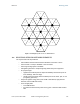
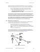
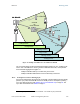
The number of degrees to offset (from vertical) the mounting hardware leg of the support
tube is equal to the angle of elevation from the lower module to the higher module (<B in
the example provided in
Figure 34).
LEGEND
b Angle of elevation.
B Vertical difference in elevation.
A Horizontal distance between modules.
Figure 34: Variables for calculating angle of elevation (and depression)
Calculating the Angle of Elevation
To use metric units to find the angle of elevation, use the following formula:
tan b =
B
1000A
where
B is expressed in meters
A is expressed in kilometers.