
User's Manual Part 1


Release8PlanningGuide
Issue2,November2007 Draft5forRegulatoryReview 129
12 ENGINEERINGYOURRFCOMMUNICATIONS
Before diagramming network layouts, the wise course is to
• anticipate the correct amount of signal loss for your fade margin calculation
(as defined below).
• recognize all permanent and transient RF signals in the environment.
• identify obstructions to line of sight reception.
12.1 ANTICIPATINGRFSIGNALLOSS
The C/I (Carrier-to-Interference) ratio defines the strength of the intended signal relative
to the collective strength of all other signals. Cyclone modules typically do not require a
C/I ratio greater than
• 3 dB or less at 10-Mbps modulation and −65 dBm for 1X operation. The C/I ratio
that you achieve must be even greater as the received power approaches the
nominal sensitivity (−85 dBm for 1X operation).
• 10 dB or less at 10-Mbps modulation and −65 dBm for 2X operation. The C/I ratio
that you achieve must be even greater as the received power approaches the
nominal sensitivity (−79 dBm for 2X operation).
• 10 dB or less at 20-Mbps modulation.
12.1.1 UnderstandingAttenuation
An RF signal in space is attenuated by atmospheric and other effects as a function of the
distance from the initial transmission point. The further a reception point is placed from
the transmission point, the weaker is the received RF signal.
12.1.2 CalculatingFreeSpacePathLoss
The attenuation that distance imposes on a signal is the free space path loss.
PathLossCalcPage.xls calculates free space path loss.
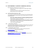
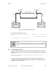
12.1.3 CalculatingRxSignalLevel
The Rx sensitivity of each module is provided at
http://Last Mile
Gear.Cyclonewireless.com/prod_specs.php. The determinants in Rx signal level are
illustrated in
Figure 31.