Carson Manufacturing Co., Inc. 5451 North Rural Street Indianapolis, IN 46220 Phone: (888) 577-6877 Fax: (317) 254-2667 www.carsonsirens.com SC-409-10 SIREN AMPLIFIER WITH LIGHT CONTROL INSTALLATION AND OPERATING INSTRUCTIONS Carson is a trademark of Carson Manufacturing Company, Inc. Sound Hazard - Sound level from siren speaker (>120dBA @ 10 feet) may cause hearing damage. Do not operate siren without adequate hearing protection for you and anyone in immediate vicinity. (Ref. OSHA 1910.
Page 2 of 16 SC-409-10 Installation and Operating Instructions TABLE OF CONTENTS GENERAL DESCRIPTION ....................................................................................3 SPECIFICATIONS .................................................................................................3 INSTALLATION .....................................................................................................4 SAFETY PRECAUTIONS ..........................................................................
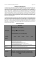
SC-409-10 Installation and Operating Instructions Page 3 of 16 GENERAL DESCRIPTION The SC-409 Light Control/Siren is a premium unit designed for single or dual 100W speaker use. The primary operating modes are Radio, Cycler, Standby, Yelp, Wail, and Phaser. A Noise Canceling PA Override and push-button Horn Override are available in all modes except Radio. A push-button is provided for toggling between Wail, Yelp, and Phaser tones, and Manual siren control in silent modes.
Page 4 of 16 SC-409-10 Installation and Operating Instructions INSTALLATION Proper installation of the unit is essential for years of safe, reliable operation. Please read all instruction before installing the unit. Failure to follow these instructions can cause serious damage to the unit or vehicle and may void warranties. SAFETY PRECAUTIONS For the safety of the installer, vehicle operator, passengers and the community please observe the following safety precautions.
SC-409-10 Installation and Operating Instructions Page 5 of 16 SWA-5 (T-T) Two-Tone - Two-Tone replaces Phaser tone by turning this switch on. SWA-6 (P_I) Phaser Inhibit - Phaser and Two-Tone tones are disabled by turning this switch on. SWA-7 (H_I) Horn Inhibit - Horn tone is disabled by turning this switch on. SWA-8 (SM) Short Manual - The Manual siren tone will normally die out and stop when Manual push-button is released. Turn this switch on to have the Manual siren tone stop immediately.
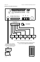
Page 6 of 16 SC-409-10 Installation and Operating Instructions AMPLIFIER CONNECTIONS +VDC HORN RING SWITCH +VDC Added SPDT Switch HORN RING SWITCH SPLICE HORN MOMENTARY FOOT SWITCH AUX HORN -VDC switching example AUX AUX Must set AUX_P option switch (2) #22 AWG BLU Connect to output jack, terminals, or speaker of radio #22 AWG GRN #22 AWG WHT +VDC Switching examples RADIO DOOR SWITCH SPLICE CUT -VDC switching example +VDC Switching example CAMERA Must set CUT_P option switch #22 AWG
SC-409-10 Installation and Operating Instructions Page 7 of 16 LIGHT CONTROL CONNECTIONS The power inputs for the light controls are separate from the power input for siren. Also the power inputs for the lever switch and six auxiliary control switches are separate. This helps prevent a fault in one main circuit from affecting another main circuit. Fuses / Breakers Each light control output is fused and should be limited to 20 Amps.
Page 8 of 16 SC-409-10 Installation and Operating Instructions LV1 SIREN FUSE LV2 LV3 SW1 SW2 SW3 SW4 SW6 RAD VOL SW5 NEG NEG VID ENA AUX RAD RAD CUT POS POS SPK SPK Auxiliary Control Switch Connections 6-P Terminal Block Plug (CP4956-06) Plug installed this orientation Load SW6 20 Amps Max. Load SW5 20 Amps Max. Load SW4 20 Amps Max. Load SW3 20 Amps Max. Load SW2 20 Amps Max. Load SW1 20 Amps Max.
SC-409-10 Installation and Operating Instructions Page 9 of 16 LEVER AND AUXILIARY CONTROL SWITCH PROGRAMMING Each position of the lever switch and the six auxiliary control switches may now be programmed once electrical connections are made and power is available to the unit. The programming mode is entered by changing an internal DIP switch. Note: The unit must be turned on and off with the switch on the enable input to program the function of each auxiliary control switch.
Page 10 of 16 SC-409-10 Installation and Operating Instructions Set Lever Switch and Auxiliary Switch Combination (Lever Switch in Position 1, 2, or 3). 1. Set the lever switch to desired position to program. 2. Press the desired auxiliary switch to change color to RED and tie it to the lever switch position Press the auxiliary switch to change color to GREEN and remove from combination. Note: The Timed Momentary (Gun Lock Timer) may not be added to combination.
SC-409-10 Installation and Operating Instructions Page 11 of 16 OPERATION Sound Hazard - Sound level from siren speaker (>120dBA @ 10 feet) may cause hearing damage. Do not operate siren without adequate hearing protection for you and anyone in immediate vicinity. (Ref. OSHA 1910.95 for occupational noise exposure guidelines) GENERAL This unit is designed for easy operation under the stress associated with high-speed pursuit. Most siren functions are accessible with one simple motion.
Page 12 of 16 SC-409-10 Installation and Operating Instructions PA - The noise-canceling microphone is used for public address operation and overrides any siren mode when the button on the side is pressed. Adjust the PA Volume and hold the microphone close to your lips for proper operation. Cutout Input (Optional) - During Installation, the cutout input may be connected to the vehicle door switch or other switching device.
SC-409-10 Installation and Operating Instructions Page 13 of 16 Video Trigger Output A video camera trigger output is activated with the lever switch in position 1, 2, or 3. Programmed auxiliary control switches will also activate trigger. See LEVER AND AUXILIARY CONTROL SWITCH PROGRAMMING section. Alert While the lever switch or auxiliary control switches are on, an alert beep is sounded every 15 seconds. Set Alert Disable option to disable. See OPTION SWITCHES section.
Page 14 of 16 SC-409-10 Installation and Operating Instructions SERVICE This unit is designed to provide years of reliable service under even the worst conditions. Many times there may appear to be a problem with the unit when the true problem is in the speaker(s), controlled devices, or improper installation. The following chart shows typical symptoms and possible causes. A blown siren fuse doesn't necessarily mean that the unit is bad.
SC-409-10 Installation and Operating Instructions Page 15 of 16 PARTS The following parts are available from Carson Manufacturing Company, Inc.
Page 16 of 16 SC-409-10 Installation and Operating Instructions RETURN If you have any questions concerning this or any other Carson product, please contact our Technical Service Department at (888) 577-6877. Many issues can be handled over the phone. We can also be reached via e-mail at service@carson-mfg.com If a product must be returned for any reason, please contact our Technical Service Department to obtain a Returned Merchandise Authorization number (RMA#) before you ship the product to Carson.