
User manual


TTISIRUCIIOII SHEET
AIID WARRAIÜTY
PIEASE READ &
FULY
AflDERSTAr,ID
I'IE IIISIRUÜIONS &WARRÄIIrY
ßETOߧ U§E
§87:UP
Before beginning
set-up
you
need
to
connect up
your
ESC
as
in Fig.1 .(When
plugging
the ESC's receiver lead into
the receiver make sure
that the signal wire
-
orange
- is facing inwards).
Calibraüng
the ESC to
your
transmitter
1.
Switch
on
your
transmitter ensuring
the throttle control
and throttle trim are
in
the neutral
position.
NOTE: lf
you
have removed the
factory
fitted
battery
connector,
(see
warranty) ensure
polaraty
is
correct.
2. Plug
your
ESC into
your
battery
pack
and turn
the ESC on
with
the on/off
switch.
The red,
green
and blue
LED's will
flash for 2
seconds
(This
is the set-up
window if
you press
the button once
whilst the
LED's
are
flashing
you
enter set'
up, if
you
let the LED's flash for 2 seconds
then stop, fhe ESe
wiil
operate
with
previously
set
values)
3. With the
LED's flashing,
press
the set button once,
this will set
your
neutral
position,
the
green
LED will light.
4. Push
the throttle control to the
full forward
position,
then
return to the neutral
position,
(This
has set maximum
forward speed
point,
the
red LED will light).
5. With the red
LED lit,
pull
the throttle
control to the full brake/reverse
position,
then return to the
neutral
position.
(This
has
set the
maximum brake/reverse
paint).The
ESC will
light the LEDs to show it is in the
neutral
position.
The ESC is now
ready
to use.
Calibntion
is
complete
and the
E$C will
pawer
the
mator!
Failsafe
mode
ln
failsafe mode the controller
returns to the neutral
position,
this is
shown by the
Red LED tlashing.
Failsafe mode
is
activated
if there
is
a loss of signal
due to being out
of
range or
not receiving
a
correct receiver signal.
Battery type se§ection
The ESC is NiCAD/NltulF{ and Lipo compatible.
To switch between
auto
t{lCADn{lllH
cut off and
auto
LIpo cutoffyou
must
press
and
hold the set button before
switching
the ESC on. With ttrre set bufton
pressed,
switch
on the
ESC using the on/off switch, the
LED's will
cycle
between blue and
green,
to
use
NiCAD/NIMH cells
release
the set button
when
the
green
LED is lit, to use Lipo cells
release the set button when
the
blue
LED is lit. The ESC
will flash all 3
LED's
then
return to the neutral
position.
The Blue LED will be on solid all
the tirne whilst being used
in
auto
Lipo mode.
Reverse mode selectian
The ESC has 2 reverse modes,
'on'and'off.
On
mode
gives
full brakes until
the model has
stopped
then engages
reverse. Off mode
removes
the
reverse function
completely allowing
the ESC to operate as a forwards and
brake only
ESC.
To switch between
'on
moda'and
'ofimode',
at any time
when the ESC is in the
neutral
position, press
and hold the
set button.
The red LED will cycle between on and off,
to
use
the
ESC in reversing mode,
release
the set
button
when
the red LED is
off.
To use the ESC in brake only
mode, release the
set
button when the
red LED is
[it.
The
ESC is ready to use.
What do the
LED's mean?
Blw & @ua IED's cyclhry
-
Battery type selection
window.
M
Lfu
cy.llng
- Reverse mode
selection
window.
R.d
e Gn.r, A
4w LED'a f,eshhrg
for 2
srcotds
-
Calibration
window.
ßrdLEDf,ash@
-
Failsafe mode.
Red
& Green
LED's
on
soJid
-
Neutral
position
in
NiCAD/NiMH mode.
Grcen
LED lit solid
-
Full forwards
position
in
NiCADllrliMH mode.
Red LED lit solid
- Full
brake/Reverse
position
in
N|CAD/N|MH mode.
Re4 Grcen & Elue
LED's on solid - Neutral
position
in
Lipo mode.
Gteen & Elwe LED's lit solid
- Full forwards
position
in
Lipo mode.
Red & B,true LED's
lit solid
-
Full brake/Reverse
position
in Lipo mode.
rc
Posit§an§ng af
your
E§C fil
the
modet
Mount
the
ESC as far away as
possible
from the receiver, using
double sided
tape or velcro.
Keep the thick
power
wires away from the antenna and other thin
wires to avoid interference
problems (See
Fig.1 for example
install).
The antenna should come
straight out of the receiver into the
antenna
tube and up out of the
model. Do not attempt to use any
part
of the model
as an antenna!
The ESC should be
positioned
to allow cooling air
to
pass
over
the heatsink, this
reduces the risk of over-ternperature shutdown.
Make
sure
your
motor is fifted
with two
(2)
motor capacitors
(0.1uF)
-
one from the negative terminal
to the can and one
from
the
positive
terminal to the can.
Wiring up @f
your
ESC rn madel
(See Fig.l)
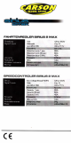
The ESCs
are
supplied with
Tamiya
style
plug
and bullet
connectors
at the factory.
(Some
of the higher
powered
versions
come fitted
with
solder
posts
and loose
wires.)
Colour coding for
the wires is as follows:
Blacke§*
{re.
Rsd=Bdt
+v6,
Bh,§§qd
{&'i?i:{lrrv,r{rvihf
'rtrr';
ALI'VAYS
DISCONNECT FROM
THE
BATTERY PACK
WI-IEN NOT SUPERVISED!
Reeeiver
Lead Conneetions
The
receiver lead on the ESC
is the JR type, see chart
below. For
some
receivers
you
may need to swap
the red and brown
wires in
the
plug.
HWTONL7
u*rylan
orcfcmal Iffi üe,llnry,yoa
,mr§t
r§,l'ora Ih3 rBd r{rr'§ fum
frß
E§Cb t@
&*d &,
ll uelng
rrro§
*xn
ont E§C ln
y,aw
m&l
§d$l
*r srerrarrwfteräa&yfü
rmüsf dcmrltrz,eel
§§ t* dft
17om.4l.tr"
§§G§
ff &afag
rnffi
üta,n
qp
E§3 !t
:otr
modal xffihs*f *, c*tlra, rtrrcfrtr
&r,@§rcrr"
ftlaf ordf
WoffteESCt
llaa üle
rsd
n&rcoaaecfud
A// ESCs
are fitted with 1 .5A
BEC unless otherwise stated.
Mtoriks Lld.
guaranteethls productlo
be
fre€
from
factory defects for24 morths from
purchase
date. vennd by
r6ceip6.
Th s d@s not cöver suibbility Io. speclfrc appli€lrons. componenb worn by use
tampenng incoii&t
@nrection, alteration b orglnal con.eclors. swllches or
wnes (apafr lrom the nting
of
an inline iuse), damage to
bäft€nes oroth6r€quipmonl through us€, hisuse or shippng damage. Our liabilily
is
lmild lo
repaning orreplacing
unils to original specifcal on. Our liability will
not oxc66d the @st ofthe
producl.
By us ng his Esc, the user accepls
all läbilily. We reseNe the il§htto modily thisguaranle wilhout noti@.
Copyright
@
Nrtroniks Ltd. 201 0
Fig.1
- installation diagram