
Technical data


181
33CZ 3V
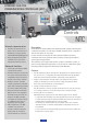
Bypass controller - compensates
for changes in supply air duct
static and responds by varying
the amount of air flow into the
return air duct or ceiling plenum.
Includes an integrated modulat-
ing actuator.
System Pilot - serves as the
user-interface and configuration
tool for the 3V zoning system.
Additionally, the System Pilot
can serve as a wall-mounted
temperature sensor for space
temperature measurement. The
occupants can use the System
Pilot to change set points and
make occupancy overrides. A
security feature is provided to
regulate access to features for
authorised users.
Zone controller - communicates
data, including zone-level require-
ments, occupancy, set points,
overrides and diagnostic infor-
mation to the zone controller in
charge of system coordination.
Includes an integrated modulating
actuator.
Universal controller – used for
integration of auxiliary building
control such as lighting, fans,
pumps, boilers and other HVAC
equipment.
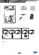
Bypass damper – opens to maintain minimum
air flow through the constant volume unit and
regulates static pressure as zone dampers close.
Zone damper – controls air flow. The damper
position is modulated for precision control of space
temperature.
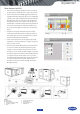
Notes
1 239 devices maximum per bus. Repeater
required every 300 m or 60 devices.
Maximum of three repeaters per bus.
2. Communication bus and sensor wiring
must be separate from AC power wiring.
3. Up to 32 total zones per system. Maximum
of five linkage coordinators with a total of
128 devices per single bus.
4. Combination CO2/T55/T56 sensor may be
used in place of T55/T56/T59 on any zone
requiring DCV. RTU must be capable of
controlling economizer for DCV conditions.
5. Locate PAT in supply air duct from air
source unit
6. System Pilot can share power with bypass
controller or VVT zone controller.
Legend
CCN Carrier Comfort Network
DCV Demand Controlled Ventilation
PAT Primary Air Temperature Sensor
RTU Rooftop unit
VVT Variable volume/variable temperature
CO2/T55/56
(optional for DCV)
(see notes 2,4)
Carrier communicating RTU
Supply air sensor
Communication
bus, shielded cable
(see notes 1, 2)
System Pilot
(see note 6)
(Use PremierLink backlit control for non-Carrier communicating RTU)
(See note 2)
24 V ac
40 VA
24 V ac
40 VA
24 V ac
40 VA
24 V ac
40 VA
24 V ac
40 VA
120 V ac
Duct sensor (locate
upstream of sensor)
Primary air sensor
Shielded cable
(see note 2)
(See note 5)
Bypass
Comm Bus
VVT linkage
coordinator
VVT Zone VVT Zone
22 zones max.
including linkage
coordinator
Comm Bus
Shielded cable
(see note 2)
T55/56/59T55/56/59T55/56/59
(optional for
linkage
coordinator)
Zone damper and controller
System Pilot
Sensor flexibility
Bypass control
Unit controllers
Universal controller