
Technical data


180
Features
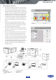
• User interface - The VVT zoning system is designed to allow a service person or
building owner to configure and operate the VVT bypass controller and zone
controllers, a linkage-compatible air source and all other networked devices
through the system pilot user interface. The System Pilot’s backlit, alphanumerical
Liquid Crystal Display (LCD) and rotary knob design allow the user to navigate
through the menus, select desired options and modify data with ease. All VVT
zoning system maintenance, configuration, setup and diagnostic information is
available through the Level II communications port to allow data access by the
System Pilot or an attached computer running the ComfortVIEW
TM
software.
• Flexibility for every application - The system maintains precise temperature
control in the space by regulating the flow of conditioned air into the space
using the zone and bypass controllers. Buildings with diverse load conditions
can be supported by controlling reheat applications, including two-position
hot water, modulating hot water, up to 3-stage electric heat or combination
baseboard and ducted heat. The VVT zoning system oers zone level flexibility
with its expanded range of compatible zone sensors - including simple space
temperature sensors up to fully network compatible devices.
• Linkage system compatibility - Linked to a Carrier linkage system, the VVT zoning
system components provide numerous features and benefits such as weighted
average demand for system operation, intelligent supply air temperature reset,
set point averaging, global set point schedule, and occupancy scheduling.
Duct static reset for the air source is provided, based on terminal requirements.
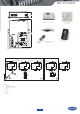
• Simple actuator connection - The VVT zone controller control assembly contains
an integral actuator assembly, field mounted to the VVT terminal damper shaft,
similar to the mounting of a standard actuator. The VVT zone controller is
designed for vertical or horizontal mounting.
• Ease of installation - The VVT zoning system components are provided with
removable connectors for power and communications. Non-removable screw
type connectors are used for inputs. The removable connectors are designed
so that they can be inserted one way to prevent installation errors. The VVT
zone controller also provides an RJ-14 modular phone jack for the Network
Service tool connection to the module via the Carrier communicating network.
Accessories
• Remote room sensors (with or
without LCD display)
• Wall- our duct-mounted CO
2
sensor
to monitor indoor air quality levels
• ComfortView software provides on-
site or remote monitoring facility
• Outdoor-air sensor (HH79NZ039)
reports the outdoor-air temperature
to the communication bus. The
information can be used to lock out
heating or cooling modes when the
temperature is not within user-
configured limits. The outdoor-air
sensor is needed when an economizer
is used.
• Supply air temperature sensor
(33ZCSENSAT) is required for heating
applications or stand-alone operation.
• Duct temperature sensor
(33ZCSENDAT) is required for use
with a bypass controller and must
be installed in the supply air duct.
Additional control features
• The VVT zoning system components
provide additional control features
such as occupied/unoccupied
scheduling initialised via the network.
The VVT zone controller oers override
invoked from a wall sensor during
unoccupied hours from 1 to 1440
minutes in 1-minute increments.
Optional Indoor Air Quality (IAQ)
control or relative humidity
monitoring are also available.
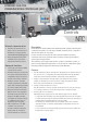
33CZ
Controls
3V PACKAGED CONTROL SYSTEM