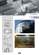
Controls Index System architecture 164
Index Type Building management system Fan coil controllers Hydronic systems Zoning systems Chilled-water plant control system Range Page Carrier Comfort Network (CCN) Comfort-View 166 168 Electronic thermostats Overview HDB controllers NTC controllers 170 171 172 174 Aquasmart Evolution 176 VVT (33CZ) Comfort Zone II 180 182 Pro-Dialog CSM III 184 186 165
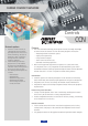
carrier comfort network Controls CCN Network options • • • Cover the essential elements of a Building Management System providing diverse facilities such as remote monitoring, collection of performance data, maintenance management and customized reporting capabilities. Performed through individual programs that can be added to the Carrier Comfort Network via individual modules which provide a diverse set of system facilities.
CCN System Managers • Carrier offers a complete line of network system products that tie multiple stand-alone products together for a fully integrated, self-adjusting HVAC system: Example: Chillervisor System Manager (CSM III) for chiller plant control CSM III Chiller System Manager CCN protocol ComfortView Supervision 167
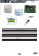
comfortview iii Controls ComfortVIEW Can perform the following tasks: Features • • • • • • • • • • • • • • • Display dynamic data in text and graphic modes Create dynamic trend plots of data from one or multiple controllers View, print, and acknowledge alarms from the network Configure operating parameters such as time schedules, set-points, and point configuration View and configure time and setpoint schedules in graphic and text mode Download and upload data to and from controllers Override the sta
ComfortVIEW III Customise your WorkSPACE screens... View critical data at once • With ComfortVIEW you can get the information you need fast. Link WorkSPACE screens in a logical progression customised for your building and management needs. • With real time trend scanning, you can visually determine how a system is behaving. ComfortVIEW allows you to easily view and record this data. • Reduce troubleshooting time with ComfortVIEW’s onscreen interaction.
electronic thermostats Controls Thermostats Electronic thermostats: The Carrier electronic thermostats are designed to control and optimise the operation of hydronic terminal fan coil units. They exist in two versions that match all terminal fan coil configurations: 2-pipe 2-pipe changeover 2-pipe and electric heater 2-pipe changeover and electric heater 4-pipe Type A x x Type B x x x Features • Fan operation - With the fan speed selector, fan mode can be set either manually or automatically.
Electronic controllers Electronic fan coil controllers - quick reference table Control algorithms On-off Proportional-integral Valve management Air flow control only (no valve) On-off actuators Proportional valves Fan control Three speeds Optimum fan speed selection Variable speed Main functions Setpoint control Occupied/unoccupied mode Frost protection mode Window contact input Measurement of water inlet temperature for automatic seasonal changeover (2 pipes) Automatic seasonal changeover (4 pipes and 2
HDB controller Controls HDB User interfaces Depending on the application, two user interface types can be selected: • a wired user interface that can be mounted on the wall or inside compatible terminal fan coils (42N) • an infrared user interface to be used together with a wall-mounted infrared received or a receiver incorporated in compatible terminal fan coils (42GW) Features • • • • • • • The HDB controller is a microprocessor-based controller designed to control and optimise the operation of h
HDB controller 56 Carrier Room Conroller (CRC2( 250 Infrared Remote Control (IR2) and receiver 190 173
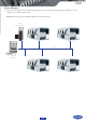
HYDRONIC FAN COIL COMMUNICATING CONTROLLER (NTC) Controls NTC Network communication Description • Carrier offers one of the market’s most sophisticated and complete communicating controllers for hydronic fan coil ranges, the NTC controller, that is compatible with the full Carrier fan coil range. For the customer and installer the same controller simplifies and eases installation and service operations whilst covering a wide range of hydronic system types and applications.
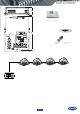
NTC controller 56 Carrier Room Conroller (CRC2( Simplified User Interface (SUI) 250 Zone User Interface (ZUI) Infrared Remote Control (IR2) and receiver 190 2 1 1 3 1 3 4a 4b 1 1 3 5 6 A Legend 1 NTC controller 2 Secondary communication bus 3 User interface connection 4 IR2 5 ZUI2 6 CRC2 A Room A B Room B 175 B
AQUASMART EVOLUTION FEATURING THE NEW SYSTEM MANAGER FOR THE AQUASMART SYSTEM Controls Aquasmart Description Features • • • Aquasmart Evolution is a complete heating, ventilating and air conditioning (HVAC) system, ideal for residential and light commercial office buildings, hotels and hospitals. It offers perfect comfort for the building occupants.
Aquasmart System design layout and configuration guide Energy savings • • • • The System Manager is connected to the system components via a communication bus, and allows control of all system and individual terminal operating parameters. System configuration is simple through easily accessible menus. Unit grouping is managed by the network and requires no specific wiring. This means the system can be easily reconfigured to suit later modifications to the occupied area.
Aquasmart New System Manager System selection • • • • • • • • • The New System Manager is a human interface that allows users to manage the Aquasmart system components and features major improvements over the previous System Manager. An intuitive colour touch screen interface facilitates access to the system parameters.
Aquasmart New features for 2011 • • • • • The Touch Pilot System Manager can now manage up to eight fresh air handling units as part of the system. The air treatment units (39SQ) supplied by Carrier are equipped with CCN controllers, they are fully integrated into the system and managed by the Aquasmart System Manager. Each fresh air plant can be associated with specific terminal fan coils and/or zones for optimum management of building use with occupancy, controlling and minimising energy use.
3V PACKAGED CONTROL SYSTEM Controls 33CZ Accessories • • • • • • Remote room sensors (with or without LCD display) Wall- our duct-mounted CO2 sensor to monitor indoor air quality levels ComfortView software provides onsite or remote monitoring facility Outdoor-air sensor (HH79NZ039) reports the outdoor-air temperature to the communication bus. The information can be used to lock out heating or cooling modes when the temperature is not within userconfigured limits.
33CZ 3V Bypass damper – opens to maintain minimum air flow through the constant volume unit and regulates static pressure as zone dampers close. Unit controllers System Pilot Bypass control Universal controller Zone damper – controls air flow. The damper position is modulated for precision control of space temperature.
comfort zone II system Controls Comfort Zone II Optional system enhancements • • • • • • • • • Programmable controller Alarm indicators Carrier command centre software Mechanical ventilation Multiple zone dampers Smart sensors Electronic air cleaners and central humidifiers Humidity control and display Outside air temperature display Features • • • • • • A zoning system providing owners of small commercial buildings with a practical way to manage energy and equipment operating costs while providing ex
Comfort Zone II Zone 1 Zone 2 Zone 4 Zone 5 Zone 3 Zone 6 Zone 8 Zone 7 1 Central control board 2 Room temperature sensor 3 Zone damper or bypass damper 4 Linear air diffusor 5 Main thermostat Other distinctive features • • • • • • • • No batteries are required System diagnostic display Time Guard to protect HVAC equipment from rapid cycling and minimum ON time feature Full system communications Barometric or motorised bypass dampers Temperature trend staging reduces operating cost Backlit displ
Pro-dialog CONTROL Controls Pro-Dialog Operator interfaces Control features (Pro-Dialog Plus/Pro-Dialog touch screen) • • • • • Clear and easy to use operator interfaces Pro-Dialog Plus interface Organisation of information around 10 menus directly accessible through hard keys Pro-Dialog touch screen interface Organisation of information around 12 menus directly accessible through soft keys and possibility to install the touch screen remotely from the chiller Pro-Dialog+ screen interface • • • •
Pro-Dialog Pro-Dialog+ screen interface Integrated features • • Pro-Dialog+ combines intelligence with operating simplicity. The control constantly monitors all machine parameters and precisely manages the operation of compressors, expansion devices, fans and of the water heat exchanger water pump for optimum energy efficiency. • Ease-of-use • Energy management • • • • Night mode: capacity and fan speed limitation for reduced noise level.
chillervisor system manager iii Controls CSM III Control functions: • • • • • • • • • • • • Automatic chiller start/stop Two seasonal chiller start/stop sequencing modes with add/drop capability Designated standby chiller support Occupancy-based plant operation with configuration override Soft loading Load balancing Bypass valve control Chilled water set-point reset Loadshed demand limiting Chiller fault handling and capacity matching System alarm messages and alarm history Short- and long-term power fa
CSM III Technical data Power requirements Operating temperature Storage temperature Operating humidity 50 VA @ 24 V ac ± 15% 0°C to 60°C -40°C to 85°C 0 to 90%, non-condensing Dimensions, mm 330 70 140 187