
Specifications

7
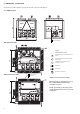
• there is adequate space above the unit for air flow and
to ensure access to the components (see dimensional
drawings).
• the number of support points is adequate and that
they are in the right places.
• the location is not subject to flooding.
• for outdoor installations, where heavy snowfall is likely
and long periods of sub-zero temperatures are normal,
provision has to be made to prevent snow accumulating
by raising the unit above the height of drifts normally
experienced. Baffles may be necessary to deflect strong
winds. They must not restrict air flow into the unit.
CAUTION: Before lifting the unit, check that all casing
panels are securely fixed in place. Lift and set down the
unit with great care. Tilting and jarring can damage the
unit and impair unit operation.
If 30RB units are hoisted with rigging, it is advisable to
protect coils against crushing while a unit is being moved.
Use struts or a lifting beam to spread the slings above the
unit. Do not tilt a unit more than 15°.
WARNING: Never push or lever on any of the enclosure
panels of the unit. Only the base of the unit frame is
designed to withstand such stresses.
Before the start-up of the refrigeration system, the complete
installation, including the refrigeration system must be
verified against the installation drawings, dimensional
drawings, system piping and instrumentation diagrams and
the wiring diagrams.
During the installation test national regulations must be
followed. If no national regulation exists, paragraph 9-5 of
standard EN 378-2 can be used as a guide.
External visual installation checks:
• Compare the complete installation with the refrigeration
system and power circuit diagrams.
• Check that all components comply with the design
specifications.
• Check that all safety documents and equipments that are
required by current European standards are present.
• Verify that all safety and environmental protection
devices and arrangements are in place and comply
with the current European standard.
• Verify that all document for pressure containers, certi-
ficates, name plates, files, instruction manuals that are
required documents required by the current European
standards are present.
• Verify the free passage of access and safety routes.
• Verify the instructions and directives to prevent the
deliberate removal of refrigerant gases.
• Verify the installation of connections.
• Verify the supports and fixing elements (materials,
routing and connection).
• Verify the quality of welds and other joints.
• Check the protection against mechanical damage.
• Check the protection against heat.
• Check the protection of moving parts.
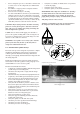
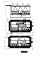
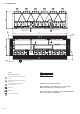
Compressor flange to be removed
Chassis fixing to be kept
• Verify the accessibility for maintenance or repair and
to check the piping.
• Verify the status of the valves.
• Verify the quality of the thermal insulation.
IMPORTANT: The compressor assemblies are “floating”
on rubber blocks between the unit chassis and the sub-
assembly chassis (they are not visible). To protect the
piping during transport, a flange is installed in the factory.
This flange must be removed on site.
The flange is identified by red rings. A label attached to
the compressor sub-assembly warns the installer.