
Specifications


47
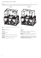
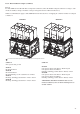
The EXV is equipped with a stepper motor (2785 to 3690
steps, depending on the model) that is controlled via the
EXV board.
The EXV is also equipped with a sightglass that permits
verification of the mechanism movement and the presence
of the liquid gasket.
Located on the EXV, permits control of the unit charge and
indicates moisture in the circuit. The presence of bubbles
in the sight-glass indicates an insufficient charge or non-
condensables in the system. The presence of moisture
changes the colour of the indicator paper in the sight-glass.
The role of the filter drier is to keep the circuit clean and
moisture-free. The moisture indicator shows, when it is neces-
sary to change the element. A difference in temperature
between the filter inlet and outlet shows that the element
is dirty.
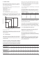
The evaporator is a shell-and-tube type with two or three
refrigerant circuits. It has been tested and stamped in accor-
dance with applicable pressure codes for a maximum ope-
rating pressure of 2910 kPa refrigerant-side and 1000 kPa
water-side. The seamless copper tubes are finned on the
refrigerant side and expanded into the tube sheets. The water
connection of the heat exchanger is a Victaulic connection.
The evaporator shell has a thermal insulation of 19 mm thick
polyurethane foam, and is equipped with a water drain and
purge. An option with an aluminium jacket is also available.
As an option the evaporator is available with frost protection
(‘evaporator frost protection’ option).
The products that may be added for thermal insulation of
the containers during the water piping connection procedure
must be chemically neutral in relation to the materials and
coatings to which they are applied. This is also the case for
the products originally supplied by Carrier SCS.
NOTES: Monitoring during operation, re-qualification,
re-testing and re-testing dispensation:
• Follow the regulations on monitoring pressurised
equipment.
• It is normally required that the user or operator sets
up and maintains a monitoring and maintenance file.
• Follow the control programmes of EN 378-2, annexes
A, B, C and D.
• If they exist follow local professional recommendations.
• Regularly inspect the condition of the coating (paint)
to detect blistering resulting from corrosion. To do
this, check a non-insulated section of the container
or the rust formation at the insulation joints.
• Regularly check for possible presence of impurities
(e.g. silicon grains) in the heat exchange fluids. These
impurities maybe the cause of the wear or corrosion
by puncture.
• Filter the heat exchange fluid check and carry out
internal inspections as described in EN 378-2, annex C.
• In case of re-testing take possible maximum pressure
differences, as indicated in (2) above into consideration.
• The reports of periodical checks by the user or opera-
tor must be included in the supervision and mainte-
nance file.
Repair
Any repair or modification, including the replacement of
moving parts:
• must follow local regulations and be made by qualified
operators and in accordance with qualified procedures,
including changing the heat exchanger tubes
• must be made in accordance with the instructions of
the original manufacturer. Repair and modification
that necessitate permanent assembly (soldering,
welding, expanding etc.) must be made using the
correct procedures and by qualified operators.
• An indication of any modification or repair must be
shown in the monitoring and maintenance file.
Recycling
The unit is wholly or partly recyclable. After use it contains
refrigerant vapours and oil residue. It is coated by paint.
Operating life
This unit is designed for:
• prolonged storage of 15 years under nitrogen charge
with a temperature difference of 20 K per day.
• 452000 cycles (start-ups) with a maximum difference
of 6 K between two neighbouring points in the
container, based on 6 start-ups per hour over 15
years at a usage rate of 57%.
Excess corrosion thickness
Gas side: 0 mm
Heat exchange fluid side: 1 mm for tubular plates in
lightly alloyed steels, 0 mm for stainless steel plates or
plates with copper-nickel or stainless steel protection.
30RB units operate with refrigerant R-410A.
30RB units are equipped with high-pressure safety
switches, calibrated to 4520 kPa.
These pressure switches are located at the discharge of
each compressor.