
Specifications


35
1
10
100
0,1 1 10
1
2
3
4
12.3.1 - Installation
The water supply of each desuperheater is arranged in
parallel.
The water connections on the desuperheater water inlets
and outlets must not cause any mechanical local constraint
at the heat exchangers. If necessary, install flexible
connection sleeves.
Install water flow control and balancing valves at the heat
exchanger outlet. Water flow control and balancing can be
done by reading the pressure drop in the heat exchangers.
This pressure drop must be identical on all of them with
the total water flow rate given by the "Electronic catalogue"
selection program.
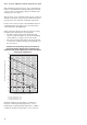
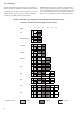
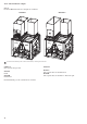
Please refer to the pressure drop curves below to carry out
the control of the balancing valves before starting up the
installation. It is possible to refine the water flow control of
each desuperheater when the unit operates at full load by
trying to obtain leaving water temperatures that are
absolutely identical for each circuit.
Heat exchanger water flow rate, l/s
1 Circuit with one compressor
2 Circuit with two compressors
3 Circuit with three compressors
4 Circuit with four compressors
Heat exchanger pressure drop, kPa
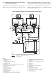
Operation of the pump (see typical diagram - item 20 of
chapter 12.3) of the desuperheater water circuit can be
linked to the start-up of the first unit compressor. This
requires the installation of an additional electronic board in
the control box: option 156, Energy Management Module.
Output No. 25 of the additional board of this option allows
control of the pump operation - the pump will start up
when the unit starts.
A flow switch (item 29) can be installed to generate an
alarm if there is a problem with the pump.
The volume of the desuperheater circuit water loop must
be as low as possible so that the temperature can increase
rapidly when the unit is started up. The minimum entering
water temperature at the desuperheater is 25°C. This may
require the use of a three-way valve (item 31), with a con-
troller and the sensor controlling the minimum required
entering water temperature.
The desuperheater water loop must include a safety valve
and an expansion tank. When selecting these, consider the
water loop volume and the maximum temperature (120°C)
when pump operation is stopped (item 20).
12.3.2 - Operating range
Entering water temperature at start-up °C 25* 75
Leaving water temperature during operation °C 30 80
Outside operating temperature °C 0** 46
* The entering water temperature at start-up must not be lower than 25°C. For
installations with a lower temperature a three-way valve is necessary.
** The minimum outside temperature is 0°C . With the winter operation option it is -
20°C.