
Specifications


34
1
2
2
6
6
5
5
4
4
7
7
8
8
^
%
&
)
q
q
q
w
w
e
o
r
t
t
t
9
!
@
!
@
$
#
W
u
p
Q
E
y
R
3
3
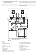
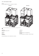
The 30RB units with the desuperheater option (No. 49) are
supplied with one heat exchanger per refrigerant circuit.
30RB unit with desuperheater option without hydfronic module
Typical installation
Border between 30RB unit and the system
1 Evaporator
2 Compressor
3 Desuperheater (plate heat exchanger)
4 Air condenser (coils)
5 Expansion valve (EXV)
6 Safety valve
7 Electric heater to protect the desuperheater against frost (not supplied)
8 Desuperheater insulation (not supplied)
9 Unit control box
10 NA
11 Desuperheater water inlet
12 Desuperheater water outlet
13 Evaporator water inlet
14 Evaporator water outlet
15 Unit with desuperheater option without hydronic module
16 System heat load
17 Border between the 30RB unit and the typical installation
20 Pump (hydronic circuit of the desuperheater loop)
21 Shut-off valve
22 Desuperheater water flow balancing and control valve
23 Safety valve
24 Expansion tank
25 Charge or drain valve
26 Air purge
27 Heat exchange coil or plate heat exchanger
28 Pressure gauge
29 Flow switch
30 Pump (sanitary hot water circuit)
31 Three-way valve + controller
32 Filter to protect the pump and the desuperheaters
33 District water supply
34 Sanitary hot water outlet
During the unit installation the heat reclaim plate heat
exchangers must be insulated and frost protected, if required.
Please refer to the typical installation diagram below for
the main components and functions of the 30RB units with
the desuperheater option.