
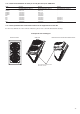
Specifications


33
3
1
1
1
X
1500
∅ 2"
1500
1500
2200
2253
2297
Y
1
2
519
519
1869
519
231
214
251
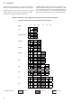
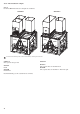
30RB 602-802
30RB X Y
602-672 5992 1200
732-802 7186 1869
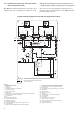
Control power user connection
Control power
connection, circuit C
Control power connection,
circuits A and B
NOTE: Non-contractual drawings.
When designing an installation, refer to the certified
dimensional drawings, available on request.
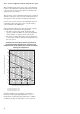
For the positioning of the fixing points, weight
distribution and centre of gravity coordinates.
Clearances required for maintenance and air flow
1
2
3
Water inlet, evaporator and desuperheater
Cylindrical gas thread,
desuperheater-side
Clearances recommended for evaporator tube removal
Clearances recommended for heat exchanger removal
Water outlet, evaporator and desuperheater
Air outlet, do not obstruct
Additional compressor(s), depending on the unit size