
Specifications


28
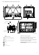
11.2.3 - 30RB 432-522 - Total heat reclaim condenser option
Power connection
For user control connection
1 Control valve
2 Air vent
3 Flow switch for the condenser (supplied)
4 Flexible connection
5 Condenser
6 Temperature sensor (supplied)
7 Drain
8 Buffer tank (if needed)
9 Filter(meshsize:1.2mm=20mesh)
10 Expansion tank
11 Fill valve
Size 522
Clearances required for maintenance and air
flow
Clearances recommended for evaporator tube
removal
Clearances recommended for heat exchanger
removal
Water inlet
Water outlet
Air outlet, do not obstruct
ATTENTION: The Victaulic flange sleeves of the conden-
ser are not installed, but supplied with the unit. The
temperature sensors and the condenser flow switch are in
the control box and wired. After connecting the Victaulic
flange sleeves, the temperature sensors must be installed,
as well as the water flow switch which must be located in
the condenser outlet.
NOTE: Non-contractual drawings.
When designing an installation, refer to the certified
dimensional drawings, available on request.
For the positioning of the fixing points, weight distribu-
tion and centre of gravity coordinates.
4” Victaulic type 75
6” Victaulic type 75
6” Victaulic
type 75
4” Victaulic
type 75
1
2
3
1
2
4
5
7
8
9
10
11
3
6
6