
Specifications


21
The water circulation pumps of the 30RB units have been
sized to allow the hydronic modules to cover all possible
configurations based on the specific installation conditions,
i.e. for various temperature differences between the entering
and the leaving water (∆T) at full load, which can vary
between 3 and 10°C.
This required difference between the entering and leaving
water temperature determines the nominal system flow
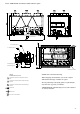
rate. It is necessary to know the nominal system flow rate
to allow its control via a manual valve provided in the
water leaving piping of the module (item 9 in the typical
hydronic circuit diagram).
With the pressure loss generated by the control valve in the
hydronic system, the valve can impose the system pressure/
flow curve on the pump pressure/flow curve, to obtain the
desired operating point. The pressure drop reading in the
heat exchanger is used to control and adjust the nominal
system flow rate.
Use this specification for the unit selection to know the
system operating conditions and to deduce the nominal air
flow as well as the heat exchanger pressure drop at the
specified conditions. If this information is not available at the
system start-up, contact the technical service department
responsible for the installation to get it.
These characteristics can be obtained from the technical
literature using the unit performance tables for a ∆T of 5 K at
the evaporator or with the Electronic Catalogue selection
program for all ∆T conditions other than 5 K in the range
of 3 to 10 K.
As the total system pressure drop is not known exactly at
the start-up, the water flow rate must be adjusted with the
control valve provided to obtain the specific flow rate for
this application.
Proceed as follows:
Open the valve fully (approximately 22 turns counter-
clockwise).
Start-up the pump using the forced start command (refer
to the controls manual) and let the pump run for two
consecutive hours to clean the hydronic circuit of the
system (presence of solid contaminants).
Read the filter pressure drop by taking the difference of
the readings of the pressure gauge connected to the filter
inlet and outlet, using valves (see typical hydronic circuit
diagrams), and comparing this value after two hours of
operation.
If the pressure drop has increased, this indicates that the
screen filter must be removed and cleaned, as the hydronic
circuit contains solid particles. In this case close the shutoff
valves at the water inlet and outlet and remove the screen
filter after emptying the hydronic section of the unit.
Renew, if necessary, to ensure that the filter is not contami-
nated. Purge the air from the circuit using the purge valves in
the hydronic circuit and the system (see typical hydronic
circuit diagram).
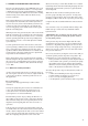
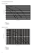
When the circuit is cleaned, read the pressures at the
pressure gauge (entering water pressure - leaving water
pressure), expressed in bar and convert this value to kPa
(multiply by 100) to find out the evaporator pressure drop.
Compare the value obtained with the theoretical selection
value.
It is essential to carry out systematic filter cleaning at the
initial start-up, as well as after any modification in the
hydronic circuit.
ATTENTION: It is essential to keep the pressure gauge
purge valve open after measuring the pressure (risk of
freezing during winter).
If the pressure drop measured is higher than the value
specified the flow rate in the evaporator (and thus in the
system) is too high. The pump supplies an excessive flow
rate based on the global pressure drop of the application.
In this case close the control valve one turn and read the
new pressure difference.
Proceed by successively closing the control valve until you
obtain the specific pressure drop that corresponds to the
nominal flow rate at the required unit operating point.
• If the system has an excessive pressure drop in relation
to the available static pressure provided by the pump,
the resulting water flow rate will de reduced and the
difference between entering and leaving water tempe-
rature of the hydronic module will be increased.
To reduce the pressure drops of the hydronic system, it is
necessary:
• to reduce the individual pressure drops as much as
possible (bends, level changes, accessories, etc.)
• to use a correctly sized piping diameter.
• to avoid hydronic system extensions, wherever possible.