
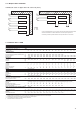
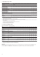
Specifications


20
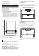
All units are equipped with a factory-set flow switch. The
unit must be interlocked with the chilled-water pump, if
the unit is not equipped with the hydronic option module.
Terminals 34 and 35 are provided for field installation of
the chilled water pump interlock (auxiliary contact for
pump operation to be wired on site).
The standard unit does not include any particular frost
protection when it has shut down. It is therefore essential
to check that there is no risk of the water in the hydronic
circuit freezing during winter temperature conditions. If
this may be the case it is essential to add an appropriate
anti-freeze solution to protect the hydronic circuit down to
the minimum temperature minus 10 K.
Another solution consists of draining the hydronic circuits
exposed to temperatures below 0°C. If the unit is not used for
an extended period, protect it by circulating a protective
solution. Please consult a specialist.
A third solution is to order the ‘evaporator frost protection’
option (factory-installed - an electric heater on the evapo-
rator). Anti-freeze solutions and heaters can be combined.
If the hydronic module option is installed, frost protection
of this module is included (electric heater).
If protection by electric heater is used, do not switch off
the power supply to the unit.
IMPORTANT: The main unit disconnect switch, the
auxiliary heater protection switch as well as the control
circuit switch must always remain closed (to locate the
components, please refer to the wiring diagram).
For this type of operation the ‘Twinning’ option must be
ordered. The units supplied are then equipped with an
additional sensor connected to the electronic board and
located in the control box. This sensor must be used when
master/slave assembly control at the water outlet is used
(it is not required for entering water control).
The customer must connect the two units via a communi-
cation bus (0.75 mm
2
, twisted and shielded). Consult the
30RB Pro-Dialog Plus control manual for the connection
addresses.
Master/slave operation is only possible, when the units are
installed in parallel. It is not possible, if the units are
installed in series.
All parameters, required for the master/slave function must
be configured using the Service Configuration menu. All
remote controls of the master/slave assembly (start/stop,
set point, load shedding etc.) are controlled by the unit
configured as master and must only be applied to the
master unit.
Each unit controls its own water pump. If there is only one
common pump, in cases with variable flow, isolation valves
must be installed on each unit. They will be activated at the
opening and closing by the control of each unit (in this case
the valves are controlled using the dedicated water pump
outputs). See the 30RB Pro-Dialog Plus Control IOM for
a more detailed explanation.
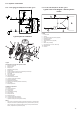
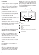
1 Master unit
2 Slave unit
Control boxes of the master and slave units
Water inlet
Water outlet
Water pumps for each unit (included as standard for units with hydronic
module)
Additional sensors for leaving water control, to be connected to channel 1
of the slave boards of each master and slave unit
CCN communication bus
Connection of two additional sensors
1
2