
Specifications


17
For the accessory system the following standardised instal-
lation methods are used, in accordance with IEC 60364,
table 52C:
No. 17: suspended aerial lines, and No. 61: buried conduit
with a derating coefficient of 20.
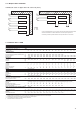
The calculation is based on PVC or XLPE insulated cables
with copper or aluminium core. The maximum temperature
is 48°C. The given wire length limits the voltage drop to < 5%.
IMPORTANT: Before connection of the main power cables
(L1 - L2 - L3) on the terminal block, it is imperative to
check the correct order of the 3 phases before proceeding
to the connection on then terminal block or the main
disconnect/isolator switch.
The current values used are given for a unit equipped with
a hydronic kit operating at maximum current.
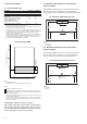
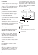
7.4.1 - Power cable entry
The power cables can enter the 30RB control box from
below or from the unit side.
• Unit raised from the ground (e.g. installation on support
rails): It is recommended to enter the power cables from
below the control box. A removable aluminium plate
below the control box allows introduction of the cables.
• Unit placed on the ground (e.g.on a concrete base): It is
recommended to enter the power cables from the con-
trol box side. An aluminium plate on the control box
face allows introduction of the cables. It is important to
check that the power cable bend radius is compatible
with the connection space available in the control box.
Refer to the certified dimensional drawing for the unit.
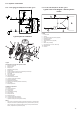
7.4.2 - Connection extension box
This accessory permits stripping the power cables before
they enter the control box, and it must be used when the
cable bend radius is not compatible with the connection
space available in the control box. The accessory connection
extension box ensures mechanical protection of the stripped
cable, before it enters the control box. It must be used in
the following cases:
2
2
2
162 1 x 240 or 2 x 150 1 x 50 180 XLPE Cu 2 x 70 225 XLPEAl
182 1 x 240 or 2 x 150 1 x 50 180 XLPE Cu 2 x 70 225 XLPEAl
202 1 x 240 or 2 x 150 1 x 70 215 XLPE Cu 2 x 95 260 XLPEAl
232 1 x 240 or 2 x 150 1 x 70 205 XLPE Cu 2 x 95 260 XLPEAl
262 1 x 240 or 2 x 150 1 x 95 178 XLPE Cu 2 x 95 260 XLPEAl
302 2 x 240 1 x 120 197 XLPE Cu 2 x 120 280 XLPE Al
342 2 x 240 1 x 120 185 XLPE Cu 2 x 150 300 XLPE Al
372 2 x 240 1 x 150 188 XLPE Cu 2 x 185 315 XLPE Al
402 2 x 240 1 x 185 190 XLPE Cu 2 x 240 330 XLPE Al
432 3 x 240 1 x 185 190 XLPE Cu 2 x 240 330 XLPE Al
462 3 x 240 1 x 240 205 XLPE Cu 3 x 185 395 XLPE Al
522 3 x 240 2 x 95 190 XLPE Cu 3 x 240 415 XLPE Al
602 2 x 240/2 x 185 1 x 185/1 x 70 190/155 XLPE Cu 2 x 185/2 x 95 430/325 XLPE Cu/XLPE Al
672 2 x 240/2 x 185 1 x 185/1 x 95 190/178 XLPE Cu 2 x 185/2 x 150 430/375 XLPE Cu/XLPE Al
732 3 x 240/2 x 185 2 x 95/1 x 70 190/155 XLPE Cu 3 x 185/2 x 95 490/325 XLPE Cu/XLPE Al
802 3 x 240/2 x 185 2 x 95/1 x 95 190/178 XLPE Cu 3 x 185/2 x 150 490/375 XLPE Cu/XLPE Al
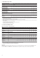
The current values used are given for a unit equipped with a hydronic kit operating at maximum current.
Refer to the 30RB Pro-Dialog Plus Controls IOM and the
certified wiring diagram supplied with the unit for the field
control wiring of the following features:
• Customer interlock (safety chain)
• Evaporator pump interlock (mandatory)
• Remote on/off switch
• Remote heat/cool switch
• Demand limit external switch 1
• Remote dual set point
• Alarm, alert and operation report
• Evaporator pump control
• Heat reclaim condenser pump control (option)
• Setpoint reset via outside air temperature sensor reset
(0-10 V)
• Various interlocks on the Energy Management
Module (EMM) board (accessory or option)
After the unit has been commissioned, the power supply
must only be disconnected for quick maintenance operations
(one day maximum). For longer maintenance operations
or when the unit is taken out of service and stored (e.g.
during the winter or if the unit does not need to generate
cooling) the power supply must be maintained to ensure
supply to the compressor oil crankcase heaters.
• Unit placed on the ground and use of power cables
with protective metallic armour.
• Unit placed on the ground and use of power cables
with a section > 250 mm
2
.
Supply cable inlet