
Specifications


16
The maximum deviation from the average is 6 V. The
greatest percentage deviation is:
100 x 6/400 = 1.5 %
This is less than the permissible 2% and is therefore
acceptable.
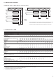
162-262 1 X (as standard)
302-522 1 -
602-802 2* -
162-262 1 X (as standard)
302-522 1 X
602-802 2* X
162-262 1 N/A
302-522 1 X
602-802 2* X
* 2 connection points: one for circuits A and B and one for circuit C
N/A - Not available
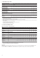
Wire sizing is the responsibility of the installer, and depends
on the characteristics and regulations applicable to each
installation site. The following is only to be used as a guide-
line, and does not make Carrier in any way liable. After
wire sizing has been completed, using the certified dimen-
sional drawing, the installer must ensure easy connection
and define any modifications necessary on site.
The connections provided as standard for the field-supplied
power entry cables to the general disconnect/isolator switch
are designed for the number and type of wires, listed in the
table below.
The calculations are based on the maximum machine current
(see electrical data tables).
Please refer to the certified dimensional drawings, supplied
with the unit.
The power supply must conform to the specification on the
chiller nameplate. The supply voltage must be within the
range specified in the electrical data table. For connections
refer to the wiring diagrams and the certified dimensional
drawings.
WARNING: Operation of the chiller with an improper
supply voltage or excessive phase imbalance constitutes
abuse which will invalidate the Carrier warranty. If the
phase imbalance exceeds 2% for voltage, or 10% for
current, contact your local electricity supply at once and
ensure that the chiller is not switched on until corrective
measures have been taken.
100 x max. deviation from average voltage
Average voltage
Example:
On a 400 V - 3 ph - 50 Hz supply, the individual phase
voltages were measured to be:
AB = 406 V ; BC = 399 V; AC = 394 V
Average voltage = (406 + 399 + 394)/3 = 1199/3
= 399.7 say 400 V
Calculate the maximum deviation from the 400 V average:
(AB) = 406 - 400 = 6
(BC) = 400 - 399 = 1
(CA) = 400 - 394 = 6
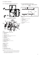
• The control box includes the following standard features:
- Starter and motor protection devices for each compressor and the fan(s)
- Control devices
All connections to the system and the electrical installations must be in full
accordance with all applicable local codes.
• The Carrier 30RB units are designed and built to ensure conformance with
these codes. The recommendations of European standard EN 60 204-1
(corresponds to IEC 60204-1) (machine safety - electrical machine components -
part 1: general regulations) are specifically taken into account, when designing the
electrical equipment.
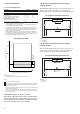
Circuit A has disconnect switches and branch sections, designed to supply the
evaporator pump power input.
• Generally the recommendations of IEC 60364 are accepted as compliance with
the requirements of the installation directives. Conformance with EN 60204 is
the best means of ensuring compliance with the Machines Directive § 1.5.1.
• Annex B of EN 60204-1 describes the electrical characteristics used for the
operation of the machines.
1. The operating environment for the 30RB units is specified below:
a. Environment* - Environment as classified in EN 60721 (corresponds to IEC
60721) :
- outdoor installation*
- ambient temperature range: -20°C to +48°C, class 4K3*
- altitude:≤2000m
- presence of hard solids, class 4S2 (no significant dust present)
- presence of corrosive and polluting substances, class 4C2 (negligible)
- vibration and shock, class 4M2
b. Competence of personnel, class BA4* (trained personnel - IEC 60364)
2. Power supply frequency variation: ± 2 Hz.
3. The neutral (N) line must not be connected directly to the unit (if necessary use
a transformer).
4. Overcurrent protection of the power supply conductors is not provided with the
unit.
5. The factory-installed disconnect switch(es)/circuit breaker(s) is (are) of a type
suitable for power interruption in accordance with EN 60947-3 (corresponds to
IEC 60947-3).
6. The units are designed for simplified connection on TN(s) networks (IEC
60364). For IT networks derived currents may interfere with network
monitoring elements, and it is recommended to create an IT type divider for the
system units that require this and/or a TN type divider for Carrier units. Please
consult the appropriate local organisations to define the monitoring and
protection elements and to complete the electrical installation.
* The required protection level for this class is IP43B (according to reference
document IEC 60529). All 30RB units are protected to IP44CW and fulfil this
protection condition.
MOTOR