
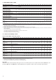
Specifications


14
3.3
-20
48
15
-10
Entering water temperature at start-up °C 6.8* 40
Leaving water temperature during operation °C 3.3 15**
Standard unit °C 0*** 48
Unit with option 28B (winter operation) °C -10 48
Unit with option 28 (winter operation) °C -20 48
Standard unit (outdoor installation) Pa 0 0
Unit with option 12 (indoor installation) Pa 0**** 200
* For application requiring operation at less than 6.8°C, contact Carrier for unit
selection using the Carrier electronic catalog.
** For an application, requiring operation up to +15°C leaving water temperature,
contact Carrier for the selection of the unit.
*** For operation up to -20°C the units must be equipped with option 28 “Winter
operation”: Moreover the unit must either be equipped with the evaporator frost
protection option or the water loop must be protected against frost by the
installer, using an anti-freeze solution.
Maximum outside temperature: For transport and storage of the 30RB units
the minimum and maximum allowable temperatures are –20°C and +48°C. It is
recommended that these temperatures are used for transport by container.
**** Unit with fans with available pressure up to 200 Pa.
Notes:
1. Evaporator∆T=5K
2. The evaporator is protected against frost down to -20°C.
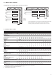
Legend:
Standard unit operating at full load.
Operating range, units equipped with options 28 and 28B “Winter operation”.
Option 28B (with two-speed lead fan for each circuit) allows operation down to
-10°C outside temperature.
Option 28 (with variable-speed lead fan for each circuit) allows operation down
to -20°C outside temperature.
Moreover the unit must either be equipped with the evaporator frost protection
option or the water loop must be protected against frost by the installer, using
an anti-freeze solution.
ATTENTION: Option 28 “Winter operation”
If the outside temperature is below -10°C and the unit has
been switched off for more than 4 hours, it is necessary to
wait two hours after the unit has been switched on again
to allow the frequency converter to warm up.
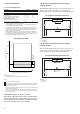
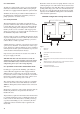
The minimum chilled water flow is shown in the table on
the next page. If the system flow is less than this, the
evaporator flow can be recirculated, as shown in the diagram.
1 Evaporator
2 Recirculation
The maximum chilled water flow is shown in the table on
the next page. If the system flow exceeds the maximum
value, it can be bypassed as shown in the diagram.
1 Evaporator
2 Bypass
Leaving evaporator water temperature, °C
Entering air temperature, °C
2
Option 28B
Option 28