
Specifications


13
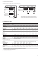
30RB 162 182 202 232 262 302 342 372 402 432 462 522
Shaft power kW 2.2 2.2 2.2 2.2 2.2 3 3 4 4 4 5.5 5.5
Power input* kW 2.7 2.7 2.7 2.7 2.7 3.6 3.6 4.6 4.6 4.6 6.3 6.3
Nominal current draw A 4.5 4.5 4.5 .4.5 4.5 6.0 6.0 7.6 7.6 7.6 10.3 10.3
Maximum current draw at 400 V** A 4.7 4.7 4.7 4.7 4.7 6.4 6.4 8.2 8.2 8.2 11.2 11.2
Shaft power kW 4 4 4 4 4 5.5 5.5 7.5 7.5 7.5 11 11
Power input* kW 4.7 4.7 4.7 4.7 4.7 6.4 6.4 8.5 8.5 8.5 12.2 12.2
Nominal current draw A 7.6 7.6 7.6 7.6 7.6 10.3 10.3 13.9 13.9 13.9 19.5 19.5
Maximum current draw at 400 V** A 8.2 8.2 8.2 8.2 8.2 11.2 11.2 15.2 15.2 15.2 21.2 21.2
Note: The water pump power input values are given for guidance only.
* To obtain the maximum power input for a unit with hydronic module add the maximum unit power input from the electrical data table in section 5 to the pump power
input* in the table above..
** To obtain the maximum unit operating current draw for a unit with hydronic module add the maximum unit current draw from the electrical data table in section 5 to the
pump current draw** in the table above.
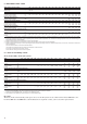
1 - - 2 - 3 - - - - - - - - - -
B 2 2 - 2 - - - 3 - 3 - - - - - -
- - - - - - - - - - - - - - - -
- 1 1 - 2 - 3 3 3 4 4 4 3 3 4 4
B - - 2 - 2 2 2 - 3 - 3 4 3 3 4 4
- - - - - - - - - - - - 3 4 3 4
I Nom Nominal current draw at Eurovent conditions (see definition of conditions under nominal unit current draw), A
I Max Maximum operating current at 360 V, A
LRA Locked rotor current, A
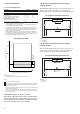
There are only power reserves on the units without hydronic
modules. The reserve is the value corresponding to the high
pressure pump capacity (see information in the hydronic
module data table). Units that do not have the hydronic
module option (30RB 602 to 802) have no reserves.
Control circuit power reserve:
The TC transformer with all possible options connected
makes 1A available for 24 V, 50 Hz.
For the same TC transformer the 230 V, 50 Hz circuit with
connection ribbon only permits supply to the battery
chargers for portable computers, 0.8 A at 230 V maximum.
IMPORTANT: Only connect doubly-insulated class II
apparatus to these ribbons.