
Specifications


11
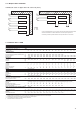
30RB 162 182 202 232 262 302 342 372 402 432 462 522 602 672 732 802
kW 163 173 193 227 263 293 328 359 391 418 447 506 596 652 704 758
kW 55.6 59 70 73 98 104 121 128 147 151 169 191 218 240 265 288
Sound power level, 10-12 W**** † dB(A)
Unit with option 15 (low noise level) 89 89 89 89 89 90 90 91 91 92 92 92 93 93 94 94
Standard unit 91 91 91 91 91 92 92 93 93 94 94 94 95 95 96 96
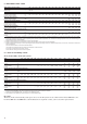
Standard unit with option 15 and high-
pressure dual-pump hydronic module option kg 1960 2040 2130 2160 2330 3070 3266 3254 3480 4010 4200 4400 - - - -
Unit with option 15 kg 1780 1860 1950 1970 2150 2770 2966 3014 3140 3670 3810 3988 5166 5344 6024 6204
Standard unit kg 1710 1780 1880 1890 2060 2660 2856 2884 3010 3520 3660 3818 4966 5135 5794 5954
R-410A
Circuit A kg 11.4 11.4 11.4 14.5 14.5 20 21 21 20.5 26 26.5 26.5 23 23 28 28
Circuit B kg 13.5 13.5 13.5 14 14 14 14 21 21.5 22 21.5 27.5 23 22.5 30 30
Circuit C kg - - - - - - - - - - - - 24 28 25 33
Hermetic scroll, 48,3 r/s
Circuit A 1 1 1 2 2 3 3 3 3 4 4 4 3 3 4 4
Circuit B 2 2 2 2 2 2 2 3 3 3 3 4 3 3 4 4
Circuit C - - - - - - - - - - - - 3 4 3 4
No. of control stages - - - - 4 5 5 6 6 7 7 8 9 10 11 12
Minimum capacity % 33 28 33 25 25 18 20 15 17 13 14 13 11 10 9 8
Pro-Dialog Plus
All aluminium micro-channel heat exchanger (MCHX)
Axial FLYING BIRD IV with rotating shroud
Quantity 3 4 4 4 4 5 5 6 6 7 7 8 9 10 11 12
Total air flow l/s 13542 18056 18056 18056 18056 22569 22569 27083 27083 31597 31597 36111 40623 45139 49653 54167
Speed r/s 16 16 16 16 16 16 16 16 16 16 16 16 16 16 16 16
Direct expansion, shell-and-tube
Water volume l 120 120 120 110 110 110 125 125 125 113 113 113 284 284 284 284
Max. water-side operating pressure
without hydronic module kPa 1000 1000 1000 1000 1000 1000 1000 1000 1000 1000 1000 1000 1000 1000 1000 1000
Pump, Victaulic screen filter, safety valve, expansion tank, pressure gauge, water + air purge valves, flow control valve
Water pump Centrifugal, monocell, low or high pressure (as required), 48.3 r/s, single or twinned dual pump (as required)
Quantity 1 1 1 1 1 1 1 1 1 1 1 1 - - - -
Expansion tank volume l 50 50 50 50 50 80 80 80 80 80 80 80 - - - -
Max. water-side operating pressure
with hydronic module kPa 400 400 400 400 400 400 400 400 400 400 400 400 - - - -
Victaulic
Diameter in 3 3 3 3 3 4 4 4 4 6 6 6 6 6 6 6
Outside tube diameter mm 88.9 88.9 88.9 88.9 88.9 114.3 114.3 114.3 114.3 168.3 168.3 168.3 168.3 168.3 168.3 168.3
Victaulic
Diameter in 3 3 3 3 3 4 4 4 4 5 5 5 - - - -
Outside tube diameter mm 88.9 88.9 88.9 88.9 88.9 114.3 114.3 114.3 114.3 139.7 139.7 139.7 - - - -
* Standardised Eurovent conditions: evaporator entering/leaving water temperature 12°C/7°C, outside air temperature 35°C, evaporator fouling factor 0.18 x 10
-4
(m
2
K)/W.
** Weight shown is a guideline only. To find out the unit refrigerant charge, please refer to the unit nameplate.
*** Standard unit: base unit without option 15 and hydronic module option.
**** In accordance with ISO 9614-1 and certified by Eurovent
† Rounded values for information only.
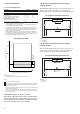
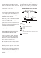
NOTE: If the walls are higher than 2 m, contact the factory
In case of multiple chillers (up to four units), the respective clearance between them
should be increased from 1500 to 3000 mm for the side space requirement.
If necessary, add the required clearances for evaporator tube or coil removal.
3000
1500
3000
1500
30003000
1500
1500
1500
A
B
B
B
B
B
B
B
B
A
A Wall
B Units