30RB 162-262 “A” 30RB 302-802 Air-Cooled Liquid Chillers Nominal cooling capacity 163-760 kW 50 Hz Unit with low-noise option shown Installation, operation and maintenance instructions
Contents 1 - INTRODUCTION...................................................................................................................................................................... 4 1.1 - Check equipment received....................................................................................................................................................... 4 1.2 - Installation safety considerations.............................................................................................
11 - TOTAL HEAT RECLAIM (OPTION 50).......................................................................................................................... 25 11.1 - Physical data for 30RB units with total heat reclaim condenser option......................................................................... 25 11.2 - Dimensions, clearances, weight distribution....................................................................................................................... 26 11.
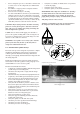
1 - INTRODUCTION 1.2 - Installation safety considerations Prior to the initial start-up of the 30RB units, the people involved should be thoroughly familiar with these instructions. After the unit has been received, and before it is started up, it must be inspected for damage. Check that the refrigerant circuits are intact, especially that no components or pipes have shifted or been damaged (e.g. following a shock). If in doubt, carry out a leak tightness check.
1.3 - Equipment and components under pressure These products incorporate equipment or components under pressure, manufactured by Carrier or other manufacturers. We recommend that you consult your appropriate national trade association or the owner of the equipment or components under pressure (declaration, re-qualification, retesting, etc.). The characteristics of this equipment/these components are given on the nameplate or in the required documentation, supplied with the products.
Comply with the regulations and recommendations in unit and HVAC installation safety standards, such as: EN 378, ISO 5149, etc. Do not use oxygen to purge lines or to pressurize a machine for any purpose. Oxygen gas reacts violently with oil, grease, and other common substances. Never exceed the specified maximum operating pressures. Verify the allowable maximum high- and low-side test pressures by checking the instructions in this manual and the pressures given on the unit name plate.
• • • • there is adequate space above the unit for air flow and to ensure access to the components (see dimensional drawings). the number of support points is adequate and that they are in the right places. the location is not subject to flooding. for outdoor installations, where heavy snowfall is likely and long periods of sub-zero temperatures are normal, provision has to be made to prevent snow accumulating by raising the unit above the height of drifts normally experienced.
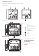
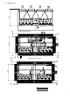
3 - dimensions, clearances For the heat reclaim condenser option, please refer to the relevant chapter. 3.1 - 30RB 162-262 Power connection With hydronic module Legend: All dimensions are in mm. 1 Clearances required for maintenance and air flow 2 Clearances recommended for evaporator tube removal 3 Clearances recommended for heat exchanger removal Water inlet Water outlet Air outlet, do not obstruct Without hydronic module For user control connection NOTE: Non-contractual drawings.
2200 2297 3.
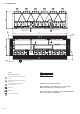
Power connection circuits A and B Power connection circuit C X 1500 1500 2253 2200 2297 3.3 - 30RB 602-802 For user control connection 1500 Legend: All dimensions are in mm 1 Clearances required for maintenance and air flow 2 Clearances recommended for evaporator tube removal 3 Clearances recommended for heat exchanger removal Water inlet Water outlet Air outlet, do not obstruct 10 30RB 602-672 732-802 X 5992 7186 NOTE: Non-contractual drawings.
3.4 - Multiple chiller installation NOTE: If the walls are higher than 2 m, contact the factory A 1500 1500 A B B B B 3000 3000 B 3000 B B 3000 B 1500 1500 Legend: A Wall B Units In case of multiple chillers (up to four units), the respective clearance between them should be increased from 1500 to 3000 mm for the side space requirement. If necessary, add the required clearances for evaporator tube or coil removal.
5 - electrical data - 30RB 30RB (without hydronic module) Power circuit Nominal power supply V-ph-Hz Voltage range V Control circuit supply Nominal unit current draw* Circuits A + B (one supply) A Circuit C (separate supply) A Maximum unit power input** Circuits A + B (one supply) kW Circuit C (separate supply) kW Cosine phi, unit at max.
5.2 - Electrical data, hydronic module 30RB Single and dual low-pressure pump Shaft power kW Power input* kW Nominal current draw A Maximum current draw at 400 V** A Single and dual high-pressure pump Shaft power kW Power input* kW Nominal current draw A Maximum current draw at 400 V** A 162 182 202 232 262 302 342 372 402 432 462 522 2.2 2.7 4.5 4.7 2.2 2.7 4.5 4.7 2.2 2.7 4.5 4.7 2.2 2.7 .4.5 4.7 2.2 2.7 4.5 4.7 3 3.6 6.0 6.4 3 3.6 6.0 6.4 4 4.6 7.6 8.2 4 4.6 7.6 8.2 4 4.6 7.6 8.
6.2 - Minimum chilled water flow (units without hydronic module) 6 - Application data 6.1 - Unit operating range Evaporator Entering water temperature at start-up °C Leaving water temperature during operation °C Condenser Outdoor ambient operating temperature Standard unit °C Unit with option 28B (winter operation) °C Unit with option 28 (winter operation) °C Available static pressure Standard unit (outdoor installation) Pa Unit with option 12 (indoor installation) Pa * Minimum 6.8* 3.
6.4 - Variable flow evaporator 6.6 - Maximum system water volume Variable evaporator flow can be used in standard chillers. The flow rate must be higher than the minimum flow given in the table of permissible flow rates and must not vary by more than 10% per minute. If the flow rate changes more rapidly, the system should contain a minimum of 6.5 litres of water per kW instead of 2.5 l/kW. Units with hydronic module incorporate an expansion tank that limits the water volume.
7 - ELECTRICAL CONNECTION Please refer to the certified dimensional drawings, supplied with the unit. 7.1 - Power supply The power supply must conform to the specification on the chiller nameplate. The supply voltage must be within the range specified in the electrical data table. For connections refer to the wiring diagrams and the certified dimensional drawings.
For the accessory system the following standardised installation methods are used, in accordance with IEC 60364, table 52C: No. 17: suspended aerial lines, and No. 61: buried conduit with a derating coefficient of 20. • • Unit placed on the ground and use of power cables with protective metallic armour. Unit placed on the ground and use of power cables with a section > 250 mm2. The calculation is based on PVC or XLPE insulated cables with copper or aluminium core. The maximum temperature is 48°C.
8 - WATER CONNECTIONS For diameters and position of the heat exchanger water inlet and outlet connections refer to the certified dimensional drawings supplied with the unit. The piping must not in any way lead to mechanical constraints on the heat exchangers. 8.1 - Operating precautions 8.1.1 - General The fluid to be cooled (often water) must meet the criteria below. The hydraulic circuit must be equipped with filters, purges, vents and unit shut-off valves.
8.2 - Hydronic connections 8.2.1 - Unit equipped with hydronic module option 8.2.
8.3 - Flow control All units are equipped with a factory-set flow switch. The unit must be interlocked with the chilled-water pump, if the unit is not equipped with the hydronic option module. Terminals 34 and 35 are provided for field installation of the chilled water pump interlock (auxiliary contact for pump operation to be wired on site). Each unit controls its own water pump. If there is only one common pump, in cases with variable flow, isolation valves must be installed on each unit.
9 - NOMINAL SYSTEM WATER FLOW CONTROL The water circulation pumps of the 30RB units have been sized to allow the hydronic modules to cover all possible configurations based on the specific installation conditions, i.e. for various temperature differences between the entering and the leaving water (∆T) at full load, which can vary between 3 and 10°C. This required difference between the entering and leaving water temperature determines the nominal system flow rate.
9.
9.
10 - FREE-COOLING SYSTEM (OPTION 118A) 30RB option 118A Nominal cooling capacity* kW Unit power input* kW Operating weight** Unit with option 15 kg Unit with option 15 + dual-pump hydronic module option kg Standard unit kg Refrigerant Circuit A kg Circuit B kg * ** 232 220 76 262 249 101 302 283 108 342 320 125 372 354 132 402 377 151 432 413 156 462 437 175 522 488 198 2398 2580 3229 3429 3518 3658 4241 4381 4591 2638 2208 2818 2390 3539 2999 3739 3199 3868 3268 3998 3398 4591 3
11 - TOTAL HEAT RECLAIM (OPTION 50) 11.1 - Physical data for 30RB units with total heat reclaim condenser option 30RB 262 302 342 372 402 432 462 522 Cooling capacity* kW 242 263 311 335 361 388 421 467 Heating capacity* kW 328 358 422 453 496 531 578 653 Unit power input* kW 91 100 117 125 142 150 166 195 Total energy efficiency ratio (EER/COP) kW/kW 2.65/3.60 2.64/3.59 2.66/3.61 2.68/3.63 2.54/3.49 2.58/3.53 2.54/3.49 2.39/3.
11.2 - Dimensions, clearances, weight distribution 2297 11.2.1 - 30RB 262 - Total heat reclaim condenser option 219 Power connection 2200 2457 1500 13 3” Victaulic type 75 500 4” Victaulic type 75 4” Victaulic type 75 341 636 1500 1 Legend All dimensions are in mm. NOTE: Non-contractual drawings.
11.2.2 - 30RB 302-402 - Total heat reclaim condenser option Power connection For user control connection 3” Victaulic type 75 4” Victaulic type 75 4” Victaulic type 75 3” Victaulic type 75 Sizes 372 and 402 Legend All dimensions are in mm. NOTE: Non-contractual drawings. 1 Clearances required for maintenance and air flow When designing an installation, refer to the certified dimensional drawings, available on request.
11.2.3 - 30RB 432-522 - Total heat reclaim condenser option Power connection For user control connection 4” Victaulic type 75 6” Victaulic type 75 6” Victaulic type 75 4” Victaulic type 75 Size 522 Legend All dimensions are in mm. 1 Clearances required for maintenance and air flow 2 Clearances recommended for evaporator tube removal 3 Clearances recommended for heat exchanger removal ATTENTION: The Victaulic flange sleeves of the condenser are not installed, but supplied with the unit.
11.6 - Heat reclaim operation 11.4 - Operating limits Heat reclaim condenser Entering water temperature at start-up °C Leaving water temperature during operation °C Condenser (air) Outdoor ambient operating temperature °C Available static pressure Pa * ** Minimum 15* 20 Minimum 0** 0 Maximum 55 55 Maximum 46 0 The heat reclaim condenser option is only available on units with two circuits. It was designed with a shell-andtube two-circuit heat exchanger with the coils in parallel.
12 - PARTIAL HEAT RECLAIM USING DESUPERHEATERS (OPTION 49) This option permits the production of free hot water using heat reclaim by desuperheating the compressor discharge gases. The option is available for the whole 30RB range. A plate heat exchanger is installed in series with the air condenser coils on the compressor discharge line of each circuit. The control configuration for the desuperheater option is factory assembled (see chapter 12.3.3 - Control configuration). 12.
12.2 - Dimensional drawings for units equipped with the desuperheater option 1068 2297 30RB 162-262 2410 Control power connection 2457 2200 Unit with hydronic module 1500 1 3 Cylindrical gas thread, O desuperheater-side Legend: 2253 All dimensions are in mm.
30RB 302-522 1068 1068 2297 Z Control power connection X 2200 Unit with hydronic module 1 1500 ∅ 2" Cylindrical gas thread, desuperheater-side 185 1 12 519 2253 519 3 1500 1 1500 740 Y Control power user connection 1500 1 3 ∅ 2" Cylindrical gas thread, 1 185 519 desuperheater-side 11 2 519 2253 2200 Unit without hydronic module Legend: All dimensions are in mm Please refer to the legend and note on the next page.
Control power connection, circuits A and B 2253 2200 519 Control power connection, circuit C X Y 1869 519 519 214 231 ∅ 2" Cylindrical gas thread, desuperheater-side 1500 1 3 1 2 1 1 1500 1500 251 2297 30RB 602-802 Control power user connection 30RB 602-672 732-802 X 5992 7186 Y 1200 1869 Legend: All dimensions are in mm. 1 Clearances required for maintenance and air flow NOTE: Non-contractual drawings.
12.3 - Installation and operation of the heat reclaim with desuperheater option During the unit installation the heat reclaim plate heat exchangers must be insulated and frost protected, if required. The 30RB units with the desuperheater option (No. 49) are supplied with one heat exchanger per refrigerant circuit. Please refer to the typical installation diagram below for the main components and functions of the 30RB units with the desuperheater option.
12.3.1 - Installation Operation of the pump (see typical diagram - item 20 of chapter 12.3) of the desuperheater water circuit can be linked to the start-up of the first unit compressor. This requires the installation of an additional electronic board in the control box: option 156, Energy Management Module. The water supply of each desuperheater is arranged in parallel.
12.3.3 - Control configuration with the desuperheater option This configuration allows the user to enter a setpoint that is relative to the minimum condensing temperature (default = 30°C) to increase the heating capacity reclaimed at the desuperheaters, if required. The percentage of the reclaimed heating capacity compared with the total capacity rejected by the condenser increases in proportion to the saturated condensing temperature.
13 - Units with fans with available pressure for indoor installation (option 12) This option applies to 30RB units installed inside the building in a plant room. For this type of installation the hot air leaving the air-cooled condensers is discharged by the fans to the outside of the building, using a duct system. The maximum fan power input for fans with a speed of 19 r/s is increased compared to that of standard fans with a speed of 15.8 r/s (the coefficient is the same as the cube of the speed ratio i.
13.1 - Installation All fans in the same refrigerant circuit are controlled by a single speed variator and therefore all run at the same speed. In 30RB units with option 12 each fan is equipped with a factory-installed connection interface, allowing the connection to the ducting system for the specific circuit (A, B and C) for each fan. Please refer to the unit dimensional drawings for the exact dimensions of the connection interface.
13.
13.3.1 - Duct installation examples Case 1 For units 30RB 162 with two V-shaped air condensers. Solution 1 Solution 2 1 1 Fan motor access hatches (provide a 700 x 700 mm hatch) for each single and dual duct Solution 1 One separate duct per fan Circuit A EV11 Circuit B EV21-EV22 Each fan discharge to the outside has its own duct.
13.3.1 - Duct installation examples (continued) Case 2 For units 30RB 182-262 with two V-shaped air condensers. Solution 1 1 1 Solution 2 1 1 1 Fan motor access hatches (provide a 700 x 700 mm hatch) for each single and dual duct Solution 1 One separate duct per fan Circuit A EV11-EV12 Circuit B EV21-EV22 Each fan discharge to the outside has its own duct.
13.3.1 - Duct installation examples (continued) Case 3 For 30RB 302 and 342 units with three V-shaped air condensers, where the middle V-shaped condenser 2 and fan EV 21 only belong to circuit A (see chapter “Number of fans per refrigerant circuit for different unit sizes”).
13.3.1 - Duct installation examples (continued) Case 4 For units 30RB 372 and 402 with three V-shaped air condensers, where the middle V-shaped condenser 2 belongs to both circuits A and B (see chapter “Number of fans per refrigerant circuit for different unit sizes”). Similar recommendations apply to units 30RB 602 and 672 that also have overlapping air condenser circuits for V-shaped condenser 2.
Similarly, the four configuration examples shown above also cover the application on the other 30RB units. IMPORTANT: The unit duct connection must not create any mechanical constraint on the fan support deck. The fan housings and the fan protection grilles must always remain in their position inside the ducts. Use bellows or flexible sleeves for the duct connection.
14 - BRINE option The frost protection value (temperature) must be used in the unit software parameters (see Carrier Service Guide). This value will allow the definition of the following limits: 1. Evaporator frost protection 2. Low pressure protection This option allows production of brine down to -10°C. The unit is equipped with reinforced evaporator insulation as well as suction pipe insulation.
15 - UNIT STORAGE ABOVE 48°C (Option 241) 16 - Major system components During transport in a closed container the refrigerant charge must be transferred to the condenser. This prevents that the pressure in the evaporator reaches the valve calibration pressure during transport (if this happened, the charge would be evacuated to the atmosphere and the unit would be empty when it arrives on site). 16.
16.5 - Electronic expansion valve (EXV) The EXV is equipped with a stepper motor (2785 to 3690 steps, depending on the model) that is controlled via the EXV board. The EXV is also equipped with a sightglass that permits verification of the mechanism movement and the presence of the liquid gasket. 16.6 - Moisture indicator Located on the EXV, permits control of the unit charge and indicates moisture in the circuit.
16.
17 - options AND ACCESSORIES Options Condenser with anti-corrosion post-treatment No.
18 - STANDARD MAINTENANCE • Air conditioning equipment must be maintained by professional technicians, whilst routine checks can be carried out locally by specialised technicians.
Level 1 • If the condensers are fouled, clean them gently in a vertical direction, using a brush. • Only work on condensers with the fans switched off. • For this type of operation switch off the HVAC unit if service considerations allow this. • Clean condensers guarantee optimal operation of your HVAC unit. This cleaning is necessary when the condensers begin to become fouled. The frequency of cleaning depends on the season and location of the HVAC unit (ventilated, wooded, dusty area, etc.).
19 - start-up cHecklist for 30RB Liquid chillers (use for job file) Preliminary information Job name:................................................................................................................................................................................................ Location:.................................................................................................................................................................................................
Unit start-up Chilled water pump starter has been properly interlocked with the chiller Oil level is correct Unit has been leak checked (including fittings) Locate, repair, and report any refrigerant leaks ................................................................................................................................................................................................................. ................................................................................................
Carry out the QUICK TEST function (see 30RB/RQ Pro-Dialog Plus Control manual): Check and log on to the user menu configuration Load sequence selection....................................................................................................................................................... Capacity ramp loading selection.......................................................................................................................................... Start-up delay.........................
Carrier is participating in the Eurovent Certification Programme. Products are as listed in the Eurovent Directory of Certified Products. This programme covers air-cooled chillers up to 600 kW and water-cooled chillers up to 1500 kW. Order No: 13439-76, 09.2008 - Supersedes order No: 13439-76, 01.2008. Manufacturer reserves the right to change any product specifications without notice. Manufacturer: Carrier SCS, Montluel, France. Printed in the Netherlands.