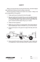
3 CAR CARRIER OPERATIONS AND MAINTENANCE MANUAL 13224 Fountainhead Plaza Hagerstown, MD 21742 Phone (717) 597-7111 www.jerr-dan.
FOREWORD This manual is intended to serve as a guide to the owner and operator in the safe operation and optimum performance of this Jerr-Dan equipment. Establishment of good operating habits and familiarity with the equipment and its capabilities combined with good judgement are essential. Before attempting to operate the unit carefully read all sections of this manual.
TABLE OF CONTENTS Certification ...................................................................................... 0.1 Safety ............................................................................................... 1.1 Decal Group ..................................................................................... 1.5 Operation .......................................................................................... 2.1 Maintenance and Lubrication ...............................................
THIS PAGE INTENTIONALLY LEFT BLANK Rev.
NOTICE MANUFACTURED BY: DATE OF MANUFACTURE_____mo. _____yr. INCOMPLETE VEHICLE MANUFACTURED BY: DATE INC. VEH. MFD. _____yr. _____mo.
THIS PAGE INTENTIONALLY LEFT BLANK 0.2 Rev.
SAFETY Safety is all-important when working with machinery. Accidents happen when established safety practices have been overlooked. Read and practice all safety points listed in this manual. Safety is the prime responsibility of the operator. 1. Read operating and loading instructions thoroughly. 2.
7. Never winch from the side of the bed. Winch only from the rear with load in line with the winch. Failure to do so can result in winch or wire rope damage. JERR-DAN DOES NOT RECOMMEND THE USE OF SIDE PULLING DEVICES. 8. Always try to winch from the center of the load. 9. Maintain winch cable in good condition. Replace when worn, kinked or frayed. Do not use cable clamps. 1.2 Rev.
10. When loading or unloading the deck and operating the winch, make certain the area behind the load is clear of personnel and obstacles. 11. Distribute load evenly on the deck. Do not concentrate the load on one section of the deck, to the rear of the truck axles, or use a tow option without a load on the deck. 12. Secure cargo to the deck at both the front and rear before the truck is driven. Do not rely on the winch as the only means of holding the load. 1.3 Rev.
13. Keep alert. Do not be distracted during any operating sequences. 14. Do not work behind truck with vehicle on deck unless vehicle is secured at front of deck. (Do not rely on winch.) 15. Read and follow wheel lift instructions for proper towing. 16. Do not exceed tow option ratings. Overloading can cause unsafe steering and braking conditions. 17. Always use both wheel straps on wheel lift. 18. Use separate safety chains from towed vehicle to subframe for tow options.
DECAL GROUP (STANDARD DECAL, LEFT SIDE) (STANDARD DECAL, RIGHT SIDE) (LUBRICATION CHART) 1.5 Rev.
(WINCH) CAUTION MAINTAIN OIL LEVEL WITHIN 1/2" OF TOP OF SIGHT GAUGE WITH ALL CYLINDERS FULLY RETRACTED. TORQUE SIGHT GAUGE BOLTS: 8 FT-LBS MAX. 272-02 (HYDRAULIC OIL LEVEL) MANUF ACTURED JL G I NDUSTRIES, FOR: IDENT. NO. MODEL VERSION MANUFACTURED BY: JLG INDUSTRIES, INC. SERIAL BY : INC. NO. FOR: UNDER ONE OR MORE OF THE FOLLOWING PATENTS: MODEL NO.
SLIDE DECK UNTIL ARROW ALIGNS WITH FIRST LEVER BEFORE TILITING (DECK ALIGNMENT) (TOW OPTION WARNING) (WHEEL LIFT WARNING) 1.7 Rev.
CAUTION FULLY RETRACT TOW OPTION BOOM TO AVOID DAMAGE DURING OPERATION OF OTHER CARRIER FUNCTIONS. 165 (TOW OPTION WARNING) (CHECKLIST REMINDER) 1.8 Rev.
(CHECKLIST) 1.9 Rev.
381 WINCH FREE SPOOL SYSTEM LOCATED UNDER MAIN DECK TO ENGAGE: LIFT UP KNOB THEN RELEASE. OPERATE WINCH TO LATCH IN. WARNING BEFORE OPERATION - WINCH CLUTCH MUST BE COMPLETELY ENGAGED WITH GUIDE BUSHING POSITIONED AS SHOWN TO DISENGAGE: LIFT UP KNOB AND PULL OUT. LOCK IN PLACE. (FREE-SPOOL OPERATION) (SLIDE PAD LUBRICATION) WARNING WINCH ORBIT MOTOR FITTINGS WILL INTERFERE WITH NYLON CABLE TRACK SYSTEM UPON INSTALLATION AND REMOVAL OF DECK.
MANUFACTURED BY: JLG INDUSTRIES, INC. FOR: 13224 Fountainhead Plaza Hagerstown, MD 21742 Phone (717) 597-7111 www.jerr-dan.com MODELNUMBER: SERIAL NUMBER: STRUCTURAL CAPACITIES* MAIN DECK CAPACITY: LBS.* UPPER DECK CAPACITY: LBS.* WHEELLIFT/TOWBAR LIFT CAPACITY: (FULL EXTENSION) LBS.* WHEELLIFT/TOWBAR TOW CAPACITY: LBS.* HITCH OPTION TONGUE CAPACITY: (FULL RETRACTION) LBS.* HITCH OPTION TONGUE CAPACITY: LBS.* *PLEASE READ THE FOLLOWING IN ORDER TO ENSURE SAFE AND CORRECT USE OF THE EQUIPMENT.
THIS PAGE INTENTIONALLY LEFT BLANK 1.12 Rev.
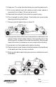
OPERATION A. Controls The operating controls for the Jerr-Dan equipment are conveniently located on both the driver’s and passenger’s side. All operators must be trained and understand the contents of the operator’s manual before operating any controls. Assure adequate operating clearance and the safety of all personnel before operating the rollback equipment. 3 5 7 9 6 4 8 10 The following controls are provided: 1. Power-take-off (in truck cab) 2. Auxiliary engine throttle control (in truck cab) 3.
1a. Set the parking brake. 1b. With the engine running, engage the PTO per instructions in the truck cab or in the PTO Operating Manual. 1c. Set the auxiliary throttle. After operating the unit several times, one will establish a feel for the optimum speed. DO NOT OVERSPEED. 2. Roll Raise the rollback handle and the deck will slide back. Roll the deck rearward approximately 12 inches to clear the mechanical hold downs at the front of the frame.
5a. Raise the winch control handle to power unreel the winch cable while a second person keeps the cable taut or disengages the winch clutch and free spool the cable. (See the Winch Operation Manual for proper clutch disengagement prodecures) 5b. Engage the winch clutch if the winch cable was free spooled. Raise the winch handle (unreel the cable)until the winch clutch fully engages. Ensure that the winch clutch is fully engaged before putting a load on the winch. 5c. Attach the winch cable to the load.
7. Roll Lower the roll control handle to roll the deck forward until the deck is in the proper position for tilting. The deck is in the proper position for tilting when the decal pointer is aligned with or just behind the roll (first) control handle. 7 8. Tilt Lower the tilt control handle to lower the front of the deck until the deck lays flat on the slide pads on the hold down. NOTE: Tilting deck when fully forward will cause damage to the hold downs. 8 9.
C. Unloading the Deck 1. Position Park the truck with the rear of the deck approximately 12 feet from desired position of vehicle being unloaded. 1a. Set the parking brake. 1b. With the engine running, engage the PTO per instructions in the truck cab. 1c. Set the auxiliary throttle. After operating the unit several times one will establish a feel for the optimum speed. DO NOT OVERSPEED. 1d. Partially release bindings of the load but maintain restraint against movement of the load in any direction.
4. Roll Raise the roll handle and the deck will slide back. Continue this operation until the approach plate has contacted the ground.Make sure that the rear bumper and the approach plate are both in firm contact with the ground before unloading. There should be an equal weight distribution between the rear bumper and the end of the deck. 4 5. Winch Winch the load off of the deck. Refer to the Winch Operation Manual for specific winch operation procedures. 5 5a.
CAUTION: Always maintain a uniform wrap of cable on the drum. “Nesting” of the winch cable may cause damager or premature wear of the winch cable. CAUTION: Remember that cables break,winches fail,and hooks become disengaged. DON’T WORK BELOW THE LOAD! CAUTION: Replace worn or damaged cables. Always wear gloves when handling cable. DO NOT USE CABLE CLAMPS! D. LOADING THE OVERCAB DECK 1.
3. Tilt Raise the tilt control lever (second lever), raising the forward end of the deck until the rear bumper rests firmly on the ground. 3 4. Roll Raise the roll handle (first lever) and the deck will slide back. Continue this operation until the approach plate of the deck has contacted the ground. Make sure that the rear bumper and the approach plate are both in firm contact with the ground before loading. There should be an equal weight distribution between the rear bumper and the end of the deck.
7. Roll (lower deck) Raise the roll handle (first lever) and move the lower deck in line with the upper deck. This will let the load slide backwards on the deck. The upper and lower deck surfaces should be in alignment. Be careful not to run the lower deck into the upper deck. The two decks should barely touch. 7 8. Winch (upper deck) Using the upper deck winch lever (sixth lever), winch the load up to the tire stops of the upper deck. Keep the winch cable taut at this point. 8 9.
E. Unloading (upper deck) Note: The main deck should be empty prior to unloading the top deck. 1. Tilting Tilt the upper deck and the lower deck into alignment. Assure that the upper deck winch cable is taut. Be sure that the load is partially unsecured prior to titlitng, but maintain restraint against movement in every direction. 1 2. Winch (upper deck) Release the remaining bindings, except for the winch cable. Winch the load down onto the main deck until it it centered about half way on the main deck.
F. Operation of the Wheel Lift (Option) The wheel lift allows an additional vehicle to be towed damage free on its own suspension by utilizing a wheel grid similar to the Jerr-Dan HPL wheel lift. The wheel lift cross bar may also be used as a conventional tow bar for badly damaged or heavier vehicles. CAUTION: Because of the additional boom extension and load point of the towed vehicle, the wheel lift places more load on the rear axle and unloads the front axle more than a conventional tow bar.
4. Set the grid width as required for the vehicle to be towed. Be sure both grids are as close to the center of the boom as possible. 5. To set the grid width, loosen the “T” handles on the front of the grid arms and pull the grids out. Be sure both grids are as close to the center of the boom as possible, and wide enough to allow the “L” arms to slide into their channels. Tighten the “T” handles to secure the grids. 6. Retract the “Cam” handle locking pin on the grid by turning it a half turn.
10. After securing the grid arm around the towed vehicles tires and before making the actual lift, check to be sure the towed vehicle’s parking brake is released, the transmission is in neutral, and the wheels are straight. NOTE: If vehicle to be towed is on a slope, do not release the brake until the tie-down straps are installed. Observe the wheels in the grid for any slippage. 11.
15. Raise the vehicle into the final towing position observing the far end for sufficient ground clearance. It is possible to set the rear of a front lifted vehicle completely onto the ground, causing damage. Take irregular roadsurfaces into consideration. Observe the lift function from the side and away from both vehicles if possible. Make sure that there are no under body components of the towed vehicle in contact with the “L” arms or wheel grid device. Readjust if necessary. 16.
CAUTION: After unloading the vehicle being towed, fully retract the wheel lift before tilting or rolling the deck. CAUTION: When not in use, wheel lift must be in upper position and fully retracted. CAUTION: The wheel lift option is designed for the transport of an additional vehicle only. Under no circumstances should a vehicle be transported on the wheel lift without a vehicle on the deck as it may cause unsafe steering and braking conditions. Single vehicle transport should utilize the deck.
TIE-DOWN STRAPS Your carrier is supplied with a set of high strength polyester web tie-down straps. They are to be used to secure wheels of the towed vehicle to the wheel lift grid. NEVER TOW A VEHICLE WITHOUT THE TIE-DOWN STRAPS INSTALLED. The tie-down strap assembly is comprised of two (2) basic components: 1. The strap 2. The ratchet spool mechanism The following steps should be followed to properly install the tiedown straps: USING THE RATCHET SPOOL MECHANISM 1.
INSTALLING THE TIE-DOWN STRAP 1. With the vehicle lifted just barely off the ground, attach the strap to the wheel grid. Be sure the hook on the ratchet is securely seated in the “L” arm. 2. Set the ratchet spool in “free spool” position and pull the webbed strap out and form a loop which will wrap around the tire. Be sure the loop is over a minimum of 1/3 of the tire. 3. Take up the slack in the strap by ratcheting the takeup spool arm. Continue until the tires show some compression. 4.
THIS PAGE INTENTIONALLY LEFT BLANK 2.18 Rev.
MAINTENANCE AND LUBRICATION Jerr-Dan rollback truck decks are designed for years of service with little maintenance. This small amount of maintenance, however, is very important for durability and for safe operation of the deck. Maintenance is an owner/user responsibility as neither the manufacturer nor the distributor can normally control this function. Use only safe practices when maintaining this equipment.
The hydraulic filter located on the return side of the hydraulic tank comes equipped with a restriction indicator gauge. This gauge shows the operator the condition of the filter element. When the needle reaches the red band (25 psi), the filter is starting to bypass and the element needs to be changed. Failure to change the element will result in premature wear and/ or failure of any or all of the hydraulic components. Only check gauge with hydraulic fluid at operating temperatures.
3.3 Rev.
TROUBLESHOOTING PROBLEM CAUSE SOLUTION PROBLEMS ENCOUNTERED WHILE UNIT IS IN TRANSIT Looseness and rattling of deck a. Loose Hold Down Blocks a. Shim Hold Down Blocks as required. WINCH FUNCTIONING IMPROPERLY Winch screeches during a. Insufficient lubrication operation Winch will not pull load a. Free spooling device on deck disengaged b. Insufficient Relief Valve pressure c. Sheared keys or broken chain at coupling d. Hydraulic pump worn Cable build-up on one a.
TROUBLESHOOTING PROBLEM CAUSE SOLUTION P.T.O. FUNCTIONING IMPROPERLY Cable tight or frozen Rattling noise in P.T.O. a. Cable kinked or bent b. Cable and P.T.O. connection not adjusted properly c. Mounting bracket nuts are over tightened at P.T.O. knob a. P.T.O. backlash too loose Howling noise in P.T.O. a. P.T.O. backlash too tight Gear oil leak between P.T.O. and pump P.T.O. will not engage or disengage a. Defective shaft seal a. Cable and P.T.O. connection not adjusted properly b.
THIS PAGE INTENTIONALLY LEFT BLANK 3.6 Rev.
5376000077- 1