Container Refrigeration Unit Data Retrieval for Micro-Link and Micro-Link 2/2i DataCORDER 62--02575--07
OPERATING INSTRUCTIONS DATA RETRIEVAL for MICRO-LINK and MICRO-LINK 2/2i DataCORDER Carrier Refrigeration Operations, A member of the United Technologies Corporation family. Stock symbol UTX. Carrier Transicold, Carrier Corporation, P.O. Box 4805, Syracuse, N.Y. 13221 U. S. A. Carrier Corporation 2000 D Printed in U. S. A.
TABLE OF CONTENTS PARAGRAPH NUMBER Page DESCRIPTION . . . . . . . . . . . . . . . . . . . . . . . . . . . . . . . . . . . . . . . . . . . . . . . . . . . . . . . . . . . . . . . . . . . . . . . . . . . . . . . 1-1 1.1 1.2 HARDWARE AND SOFTWARE . . . . . . . . . . . . . . . . . . . . . . . . . . . . . . . . . . . . . . . . . . . . . . . . . . DataCORDER . . . . . . . . . . . . . . . . . . . . . . . . . . . . . . . . . . . . . . . . . . . . . . . . . . . . . . . . . . . . . . . . . 1.2.
TABLE OF CONTENTS (Continued) PARAGRAPH NUMBER Page TOPIC 11 CONTROLLER CONFIGURATION . . . . . . . . . . . . . . . . . . . . . . . . . . . . . . . . . . . . . . . . . . . . . . . . . 3-14 Fixed Configuration Variables . . . . . . . . . . . . . . . . . . . . . . . . . . . . . . . . . . . . . . . . . . . . . . . . . . . . . . . . . . Custom Controller Configuration . . . . . . . . . . . . . . . . . . . . . . . . . . . . . . . . . . . . . . . . . . . . . . . . . . . . . . . .
LIST OF ILLUSTRATIONS FIGURE NUMBER Page Figure 1-1. Micro-Link 2 Controller and DataCORDER . . . . . . . . . . . . . . . . . . . . . . . . . . . . . . . . . . . . . . . Figure 1-2. Micro-Link 2i Controller/DataCORDER . . . . . . . . . . . . . . . . . . . . . . . . . . . . . . . . . . . . . . . . . . Figure 1-3. Micro-Link 1 Controller . . . . . . . . . . . . . . . . . . . . . . . . . . . . . . . . . . . . . . . . . . . . . . . . . . . . . . . Figure 2-1. Communication Cable Connections . . . . . . . . .
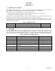
SECTION 1 DESCRIPTION 1.1 HARDWARE AND SOFTWARE This manual contains information on the Carrier Transicold DataView Program and its interface with the DataCORDER. The DataView program is used to retrieve data stored in the DataCORDER. Data retrieval can be accomplished with one of the following devices: 1. Stand-alone DOS based portable personal computer (PC) with appropriate cable and software 2.
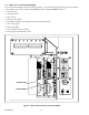
1.2.1 Micro-Link 2 Controller/DataCORDER The Carrier Transicold Micro-Link 2 Controller (see Figure 1-1) is a custom-designed, microprocessor-based control system which is fitted with a separate DataCORDER module. The DataCORDER consists of: 1. Microprocessor 2. Program memory 3. Data memory 4. Real time clock (RTC) 5. Six thermistor inputs (2 Air Temperature and 4 Cargo Temperature) 6. Two voltage inputs 7. Four status LED’s 8. Two communication ports (serial) 9.
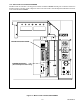
1.2.2 Micro-Link 2i Controller/DataCORDER The Micro-Link 2i Controller is an integrated Controller and DataCORDER assembly, but is otherwise identical to the Micro-Link 2 Controller. Scroll compressor units are also fitted with a controller Expansion Module located next to the Controller/DataCORDER. CONTROLLER/DataCORDER EXPANSION MODULE (Scroll Compressor Units Only) Figure 1-2.
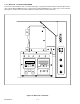
1.2.3 Micro-Link 1 Controller/DataCORDER The Carrier Transicold Micro-Link 1 Controller (see Figure 1-3) predates the Micro-Link 2 Controller. Micro-Link 1 units with the DataCORDER option are equipped with a DataCORDER that is an integral part of the Controller. Interrogation of Micro-Link 1 and Micro-Link 2 Controllers will have some differences. Figure 1-3.
1.2.4 DataCORDER Capabilities (Micro-Link 2 and Micro-Link 2i only) The Carrier DataCORDER is a flexible recording device with the following capabilities: a. Sensors Up to six thermistor temperature probes can be connected directly to the DataCORDER. These probes are referred to as: 1. Supply 2. Return 3. USDA 1 4. USDA 2 5. USDA 3 6. Auxiliary Cargo Probe On separate DataCORDER modules (Micro-Link 2 only) there are also two 0-5vdc inputs available for future expansion.
1.3 DataCORDER INTERFACE The DataCORDER is capable of performing the following functions initiated by the DataView Program 1.3.1 Data Extraction a. Daily Header Data Recorded days are presented in the following format: 1. Day 1 date (month, day, year), sensor data, events, ... 2. Day 2 date (month, day, year), sensor data, events, ... b. Sensor Data Sensor data will be read based on either standard or generic configuration.
Table 1-3. Temperature Controller Events -- Continued Event Trip Start (TS) USDA Trip Comment Pre-Trip Data Economy Mode Start (ECON_S) Economy Mode End (ECON_E) ISO Trip Comment Changed Bulb Mode Start (BULB_S) When Event Occurs Data Sent Limits Any time trip start is entered When entered with interrogation device Any time a Pre-Trip test is completed and Controller is configured to send individual test data Any time economy mode is initiated Any time economy mode is terminated.
Table 1-4 DataCORDER Events -- Continued Event Power ON (ON) Data Retrieval Real Time Clock Change RTC Battery Replaced Controller Not Responding (NWF) Controller Responding (NWR) DataCORDER Configuration Reset Probe Calibration When Event Occurs Data Stored Restoration of AC power with no battery pack present Extraction of data from the DataCORDER User modifies the real time clock (RTC) Real Time Clock (RTC) battery internal to DataCORDER is replaced DataCORDER attempted to communicate with Controller,
Table 1-5 Controlled Atmosphere (CA) Events Recorded in the DataCORDER -- Continued Event When Event Occurs Data New calibration value; Result (pass, fail, or low) Source (keypad, communications, or timer) New calibration value; Result Whenever O2 Gas Cal(pass or fail) Source (keypad, O2 Gas Calibration ibration is completed communications, or timer) New calibration value; Result Whenever CO2 Zero Cal- (pass or fail, no gas) Source (keyCO2 Zero Calibration ibration is completed pad, communications, or ti
1.4 USDA RECORDING A special type of recording is provided for USDA cold treatment purposes. Cold treatment recording requires that three remote temperature probes are placed in the cargo at various locations. Provision is made to connect these probes to the DataCORDER via receptacles located at the rear left-hand side of the unit. Four (five, on some units) receptacles are provided. Four (three-pin) receptacles are for the probes and one (five pin) receptacle is provided for the Interrogator.
SECTION 2 SYSTEM SETUP 2.1 HARDWARE PLATFORMS SUPPORTED The DataView Software will run on a variety of DOS based machines. We recommend the use of a desktop or laptop machine with at least 3MB free disk space and a VGA monitor for displaying graphics, for most printing and report generation functions. Other, less capable computers may be used for the actual data extraction. 2.2 INTERROGATION CABLES Cable requirements may differ between interrogation devices. For cable connections see Figure 2-1.
2.3 PRINTER SUPPORT Formatted reports can be generated on the following printers: 1. EPSON 85 dot matrix or compatible (most dot matrix printers will support this format) 2. HP LaserJet or equivalent (Many laser printers will support this format). For printers that are not compatible with the above printers, select the FILE printer port option in printer setup. This will send the report to an ASCII print file. 2.3.
SECTION 3 DATAVIEW PROGRAM INSTRUCTIONS NOTE The following is a copy of the software program at time of printing. If loading only one program (12--00413 reciprocating unit interrogation or 12--00528 scroll unit interrogation program) the program disc instructions may be followed as written. If loading both programs on the same computer, different resident directories must be created Where these differences exist, annotation has been added to the text provided herein.
Printers Supported 1. EPSON 85 dot matrix or compatible (most dot matrix printers support this format). 2. HP Laser Jet or equivalent (many laser printers support this format). For printers that are not compatible with the above printers, select the FILE printer port option in printer setup. This will send the report to an ASCII print file. TOPIC 2 DESKTOP QUICK START This section describes the installation procedure for the DOS DataView interrogator program.
i) Creates the sub directory C:\“directory”\DATA, where “directory” is the directory defined in step c. This is the working directory where the DCX files are stored. j) Creates the sub directory C:\“directory”\PRN_FLS, where “directory” is the directory defined in step c. This is the print file directory where the ASCII Text print files are stored. k) The user shall be notified when the installation is complete via the Installation Completion Screen and given directions on how to proceed.
To modify the CONFIG.SYS file, the following entries must be in the CONFIG.SYS file to execute the DataView program: i. DEVICE = \DOS\HIMEM.SYS ii. DEVICE = \DOS\EMM386.EXE X=C800--CFFF I=DOOO--DFFF V iii. DEVICE = \DOS\POWER.EXE iv. DEVICE = \DOS\INTERLINK.EXE v. DOS = HIGH, UMB vi. FILES = 40 vii. BUFFERS = 30 The other entries should have “REM” entered before each entry. This will retain the information in the file, but the entry will not be executed. For example; the entry, “DEVICE = \PCM\DPMS.
Throughout the program two major types of menus are used: 1. Check boxes allow the selection of all menu items that apply and look like this: [ ] Graph [X] Tabular Data [ ] Raw Events 2. Radio buttons allow the selection of only one item and look like this: (*) Metric Units ( ) Standard Units To select or deselect an item in either of these two menu’s, use the UP and DOWN arrow keys to highlight the selection and press to select.
Go -- Allows the user to start the RAW to DCX file conversion. The following steps are processed: 1. The Raw File Conversion screen is cleared. 2. The File Processing popup is displayed. 3. Each file in the current directory is checked to verify if it is a RAW formatted file. If not, it skips this file and checks the next file. 4.
TOPIC 6 MAIN MENU SCREEN This section describes the features available from the main menu. The following screen will be displayed when the program starts up. The following is a summary of the options available to the user: Interrogate -- This will allow the user to extract the data from the Recorder. The available interrogation methods are: By Trip, By Date, Last 30 Days, and All Data.
TOPIC 7 INTERROGATION MENU This section describes how to retrieve data from the recorder. The following screen is displayed when this option is selected. The following is a summary of the options available in Interrogation. By Trip -- All data logged from the Trip Start selected until the next Trip Start (or the last date in the recorder) will be downloaded. By Date -- All data logged between two user specified dates will be downloaded.
TOPIC 8 DATAREADER The DataReader Interface program communicates with the DataReader. It provides the user with the ability to view the files on the DataReader, read the files from the DataReader and store the data into the DCX file format on the users computer. The program also allows the user to erase all the files on the DataReader. The following screen is displayed when this option is chosen. The following is a summary of the options available in DataReader Interface Utility.
TOPIC 9 SYSTEM TOOLS The system tools screen provides the user with the ability to view and/or modify the recorder and controller data values. The following screen is displayed when this option is chosen. The following is a summary of the options available in System Tools.
TOPIC 10 CONTROLLER UTILITIES This section describes the features available on the controller utilities. View/Change Container ID This will allow the user to view and modify the current container ID read from the controller. Upon changing the container ID, the new ID is sent to the controller, the DataView program informs the user that the container ID was successfully sent, and returns the user to the System Tools Screen. The following screen is displayed when this option is chosen.
Control Setpoint This will allow the user to view and modify the current control setpoint being read from the controller. Upon changing the setpoint, the new setpoint value is sent to the controller, the DataView program informs the user that the setpoint was successfully sent, and returns the user to the System Tools Screen. The following screen is displayed when this option is chosen. Upon pressing to Cancel, the setpoint is canceled and the user is returned to the System Tools Screen.
Control Parameters The following screen is displayed for the user to view and modify the current settings of the controller user selectable parameters. The following is a summary of the options available in Controller Parameters. Defrost Interval -- Allows the user to view and modify the automatic defrost interval. Units -- Allows the user to view and modify the temperature units which are used when displaying controller temperature sensors.
TOPIC 11 CONTROLLER CONFIGURATION The Controller Configuration allows the user to view and modify the current controller configuration. The current model configuration, the selectable configuration variables, and the fixed configuration variables are listed. The user can select another model configuration and modify the selectable configuration variables. The following screen is displayed when this option is chosen. The following is a summary of the options available in Controller Configuration.
Fixed Configuration Variables Allows the user to view the fixed configuration variables for the selected configuration model. These variables describe the refrigeration unit and cannot be modified by the user. The following screen is displayed when this option is chosen. The following is a summary of the options available in Fixed Configuration Variables. Configuration Available -- This lists the models available for the controller.
Custom Controller Configuration Allows the user to change the selectable configuration variables and save those values into a new configuration model. The following screen is displayed when this option is chosen. The following is a summary of the options available in Custom Controller Configuration. Dehumidification -- Allows the user to configure or not configure the controller with a dehumidification device. Defrost Interval Save -- Allows the user to save or not save the defrost interval.
Help -- Displays the help screen. Cancel -- Cancels the changes to the custom controller configuration and returns the user to the Controller Configuration Screen. TOPIC 12 RECORDER UTILITIES This section describes the features available on the recorder utilities menu. Trip Functions This feature will allow the user to initiate a Trip Start and enter specific Trip comments. The following screen is displayed when this option is chosen.
Configuration This allows the user to modify the recorder configuration. For a full description of the configuration selections and illustrations of the applicable screens, refer to TOPIC 13.
Date And Time This allows the user to view and/or modify the recorder date and time. The computer time and date are displayed as an aid to the user. The following screen is displayed when this option is chosen. The recorder date is displayed in Greenwich Mean Time (GMT). The user enters the date and time, the date and time is sent to the recorder, the DataView program informs the user that the date and time was successfully sent, and returns the user to the System Tools Screen.
Update ISO Trip Header This allows the user to view and/or modify the data recorder ISO trip header. Each field has a maximum size of 13 characters. A maximum of 128 total characters are allowed. The date and time are initialized from the current date and time on the data recorder. The following screen is displayed when this option is chosen. The user enters the trip header fields, one at a time. Upon pressing the current field is accepted and the cursor is moved to the next field.
TOPIC 13 RECORDER CONFIGURATION The Recorder Configuration allows the user to view and modify the current recorder configuration. The Recorder Configuration screen shows all of the sensors installed to a unit and whether they are configured to be recorded. It also shows the recording interval. The following screen is displayed when this option is chosen. The following is a summary of the options available in Recorder Configuration.
Standard Configuration This feature will allow the user to select a standard recorder configuration, set the alarms, set the sample type for the recorder sensors, set the sample size for the recorder sensors, and set the sample type for the controller sensors. The following screen is displayed when this option is chosen. The following is a summary of the options available in Standard Configuration. Standard Configuration -- Allows the user to select the configuration.
Generic Configuration The Recorder Generic Configuration allows the user to view and modify the current recorder configuration. The Recorder Generic Configuration screen shows all of the sensors installed to a unit and whether they are configured to be recorded. It allows the user to modify the recording interval, recorder sensors, and controller sensors. The following screen is displayed when this option is chosen. The following is a summary of the options available in Recorder Generic Configuration.
Recorder Sensors This displays the active sensors connected to the recorder. It also displays the sample type and sample size configuration for each sensor. The following screen is displayed when this option is chosen. The following is a summary of the options available in Recorder Sensors Configuration. Recorder Sensors -- Allows the user to select one or all of the sensors for the recorder configuration.
Controller Sensors This displays the active sensors connected to the controller. It also displays the sample type and sample size configuration for each sensor. The following screen is displayed when this option is chosen. The following is a summary of the options available in Controller Sensors Configuration. Available Sensors -- Allows the user to select a total of eight controller sensors for the recorder configuration. Controller Sensors -- Displays the controller sensors selected.
TOPIC 14 PROBE CALIBRATION Describes how to calibrate the probe sensors. Probe calibration allows the user to calibrate the probe sensors using two different methods; external and internal. The following screen is displayed when this option is chosen. The following is a summary of the options available in Probe Calibration.
Select Probes -- Allows the user to select which probes to calibrate. Only used for external and internal probe calibration.
TOPIC 15 CONTROLLER MONITOR The controller monitor program displays the activity of the controller data. This program allows the user to view the controller data in real time to enable an overview of the container unit operation to be obtained when trouble shooting. The following screen is displayed when this option is chosen. The following is a summary of the options available in Controller Monitor program. Sensors -- Displays the current value of the controller sensors.
TOPIC 16 PROGRAM SETUP This section describes the features available to customize the computer for this program. Which allows the user to setup the working environment of DataView program on the computer. The following screen is displayed when this option is chosen. The following is a summary of the options available in Program Setup. Directories -- This allows the user to select Directories in which to save Data and Print files. The working directory is where the interrogated data is stored.
TOPIC 17 DIRECTORY SCREEN The directory screen allows the user to change the current, working, or print file directory to another directory location. The directory screen is available from the Program Setup, Interrogation, and Raw to DCX Conversion screens. The following screen is displayed when this option is chosen. Cancel -- Cancels the printer setup and returns the user to the Program Setup Screen.
TOPIC 18 PRINTER SETUP Describes the features available to setup the program to print a job. This allows the user to setup the printer port, select which printer, and select the paper size for the print jobs sent to the printer. The following screen is displayed when this option is chosen. The following is a summary of the options available in Print Setup.
Printer Port -- This allows the user to select the port that the printer will be connected to.
TOPIC 19 VIEW DATA Describes the features available to view the interrogated data. This allows the user to Display any data file (*.dcx) stored in the current working directory. A *.dcx data file is the interrogation file for one specific recorder for a single interrogation operation. The name of the file is the 6 digits of the container ID, with two letters added to uniquely define the file. For example, the container unit CTDU1234565 when interrogated would create the interrogation file name, 123456AA.
TOPIC 20 SENSOR CONFIGURATION This section describes the features available to configure the sensors. This allows a user to configure the sensors which will be used to view and print the interrogated data. The following screen is displayed when this option is chosen. The following is a summary of the options available in Sensor Configuration. DCX File Sensors -- This displays the available sensors found in the DCX file. Configurations -- This displays the sensor configurations.
TOPIC 21 TEXTUAL DATA The textual data display screen will display the interrogated data file on the screen. The data can be presented in the following ways: sensor data, event data, summary data and raw data. Sensor Data The sensor data is displayed in a tabular form, with the following columns: 1. Date 2. Time 3. Sensor 1 4. Sensor 2 5. Sensor 3 6. Sensor 4 7. Sensor 5 8. Sensor 6 9. Event Messages are displayed using acronyms to reduce space.
A valid sensor data value is displayed as a numeric value. An out of range sensor data value is displayed as “OUTRNG.” A sensor data value which has been turned off is displayed as “OFF.” NOTE Alarm numbers are not shown next to the alarm events (i.e., AL, dAL, CA_AL) when viewing sensor data. To refer to the alarm numbers view event or raw data. Event Data The event data for each day is displayed as follows: 1. Date 2. Setpoint for the day. 3. Time and event 1 which occurred. 4.
8. Point of Destination 9. Discharge Date 10.Trip Comment Daily Data: Each Day will have a record with the following data: 1. Main Setpoint at the start of the day 2. Sensor Data 3. Event Data Some days may require more than one record, if there is a lot of sensor data, or the recording format changes. The data display screen supports the following options, to move through the file: 1. Page Up Go up one page 2. Page Down Go down one page 3. Up Arrow Go up one line 4. Down Arrow Go down one line 5.
TOPIC 22 GRAPHIC DATA This enables the user to display a graph whose X axis is a time axis. The date range displayed can be selected from the view data screen and can be any portion of the available data. The Y axis gives the temperature readings. The temperature unit is selected from the program setup screen and supports both degree F and degree C. The plot is drawn from the sensors in the configuration that was chosen by the user. For information on sensor selection, refer to TOPIC 20.
TOPIC 23 PRINT DATA This will allow the user to Print any data file (*.dcx) stored in the current working directory. A *.dcx data file is the interrogation file for one specific recorder for a single interrogation operation. The name of the file is the 6 digits of the container ID, with two letters added to uniquely define the file. For example, the container unit CTDU1234565 when interrogated would create the interrogation file name, 123456AA.DCX.
Sensors -- This allows the user to choose a specific sensor configuration. The user can also choose New configuration to create a new configuration with desired sensors and then save it into the sensors.cnf file. The Available Configurations Menu will be updated to include the new configuration. Several configurations can be created and then saved in the sensors.cnf file for later usage. For further information, refer to TOPIC 20.
SECTION 4 OPTIONAL HARDWARE 4.1 DataReader The DataReader (see Figure 4-1) is a simple to operate hand held device designed for the primary purpose of extracting data from Container Systems and then uploading that data to a PC. It has the ability to store multiple data files. DataReader OFF ON Esc ENTER Figure 4-1. Hand Held DataReader 4.2 OPERATOR INTERFACE The operator interface is kept simple by the use of user selection menus.
4.3 MENU INTERFACE The DataReader is not password protected. Connection to the Controller is automatic and the user is not required to specify the Controller type (ML 1/2/2i). The first menu presented to the operator will be the DataReader menu and basic utilities (see Figure 4-2). Connect to.. ML 1/2/2i Transfer Data File Utilities DataSet Files Set Date/Time Power OFF Figure 4-2.
4.3.4 Set Date/Time Set Date/Time is used to set the date and time of the DataReader. It is important for the user to enter the correct date and time before beginning any operation. When retrieving data files from a Micro-Link 1 Controller, the date and time information are taken from the extracting device (the DataReader or laptop PC). at the menu prompt. Press again to change the date and time.
4 Extract All Data -- Valid for ML 1/2/2i Allows the user to extract all data stored in the Controller memory. Different container files found in the memory will be stored under different container numbers. b. Command Selecting Command presents the user with another menu of available functions (see Figure 4-6). Mark Trip Start Calibrate Probes Date and Time (D/C) Container ID Configuration Figure 4-6. Command Menu The user can select the desired function by pressing or and .
Display Cfg File Configure Figure 4-7. Configure Menu To view a particular configuration file, select Display Cfg File and press press to view the file. .Use the arrow keys to select the file and to view the list of available configuration files. Using the To configure a container, select Configure and press arrow keys, select desired file and press to send the configuration to the Controller. The new configuration will take effect on Controller reset (power ON). c.