
Installation Guide


X
O
6.1 Installation Place
6. OUTDOOR UNIT INSTALLATION
There is enough room for installation and maintenance.
The air outlet and the air inlet are not impeded, and can
not be reached by strong wind.
The installation area must be a dry and well ventilated
place.
The support should be flat, horizontal and can with stand
the weight of the outdoor unit. There should be no
additional noise or vibration.
The unit or the placement of the unit should not impede
on the safety or disturb the comfort of others nearby.
The connecting pipes and cables are easy to install.
Determine the air outlet direction where the discharged
air is not blocked.
There is no danger of fire due to leakage of inflammable
gas.
The piping length between the outdoor unit and the indoor
unit may not exceed the allowable piping length.
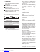
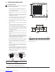
In case the installation place is exposed to strong wind
such as a seaside, make sure the fan operates properly
by putting the unit lengthwise along the wall or use a dust
shield.(Refer to Fig.6-1)
If possible, do not install the unit where it is exposed to
direct sunlight.
If necessary, install a blind that does not interfere with the
air flow.
During the heating mode, the water drains off the outdoor
unit. The condensation should be drained away from the
unit through the drain hole to an appropriate location to
avoid contact with people, plants, or animals.
Select the position where the unit will not be subject to
snow drifts, accumulation of leaves or other seasonal
debris. If unavoidable, please cover it with a shelter.
Locate the outdoor unit as close to the indoor unit as
possible.
If possible, please remove the obstacles nearby to
prevent the unit's performance from being impeded by a
lack of air circulation.
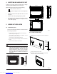
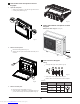
The minimum distance between the outdoor unit and
obstacles described in the installation chart does not
mean that the same is applicable to the situation of an
airtight room. Leave open two of the three
directions.(Refore to Fig.6-3)
Fig.6-1
The outdoor unit should be installed in the location that
meets the following requiements:
All the pictures in this manual are for illustration
purposes only. They may differ slightly from the air
conditioner you purchased(depending on the model).
NOTE
Strong wind
Fig.6-2
Fig.6-3
Refore to Fig.6-2~Fig.6-3
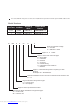
Table 6-1 Unit:in/mm
(in=mm/25.4)
32.0 (810) 22.0 (558) 82.5 (37.4)12.2 (310)
11.4 (290)
20.9 (530)
8
Downloaded from www.Manualslib.com manuals search engine