
Floor Console Indoor Unit Data Sheet

13
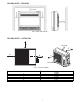
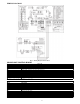
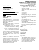
WIRING DIAGRAM
Fig. 7 – Wiring Diagram Sizes 9 and 12
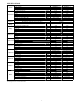
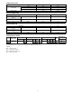
INDOOR UNIT CONTROL BOARD
Indoor unit
CODE PART NAME
CN1 Input: 230VAC High voltage Connection of the terminal
CN2 `Input: 230VAC High voltage Connection of the terminal
CN3 Output: 24VDC Between CN2 Connection of the S signal
CN6 Output: 12VDC Connection of the Lower outlet swing motor
CN7 Output: 5VDC Connection of the Room and Pipe temperature
CN10 Output: 12VDC Connection of the Display board
CN13 Output: 12VDC Connection of the Upper outlet swing motor
CN15 Output: 1-5VDC Connection of the Switch board
CN16 Output: 320VDC Connection of the Fan high voltage
CN20 Output: 5VDC Connection of the Net module
CN23 Output: 1-12VDC Connection of the Remote switch
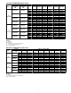
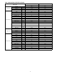
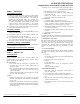
OUTDOOR UNIT CONTROL BOARD
Outdoor unit
CODE PART NAME
CN31 Output:Pin5&6(12V) Pin1-Pin4:Pulse waveform,(0-12V)
CN21 Input:Pin3-4 (3.3V) Pin2(0V),Pin1,Pin5(0-3.3V)
CN22 Input:Pin1 (3.3V) Pin2(0-3.3V)
CN37 Output: 230VAC High voltage
CN9-1,CN32-1 Output: Connection of the high voltage
CN1 Input:230VAC High voltage
CN2 Input:230 VAC High voltage
CN3 Connection to the earth
CN16 Output: Connection of the high voltage
CN26,CN27 Output: High voltage for 4-way control
CN7 Output: Pulse(0-320VDC) for DC FAN
UVW Output: Pulse(0-320VDC) for COMPRESSOR