
Duct Split System Data Sheet


22
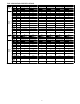
Fig. 12 – Wiring Diagram Size 48
CODE PART NAME Outdoor unit (main board)
Indoor unit CN1,CN3 Power i nput: 230V AC
CN1
Input: 230VAC High voltage Connection of the
terminal
CN2,CN4 Output: Power output for DRIVER BOARD (230V AC)
CN2
Input: 230VAC High voltage Connection of the
terminal
CN5 Input: Communication Main board and IPM Board, Pin1(5V DC )
CN3 Output: 0V Connection of the earth CN6 Input: DC FAN motor1 and DC FAN motor2 control, (Pi n7 5V DC)
CN5
Output: 0-5VDC Connection of the Water level
switch
CN8,CN9,CN12 Input: Temperature sensor (5V DC)
CN6
Output: 5VDC Connection of the Room and Pipe
temperature
CN10 Input: Pressure test (5V DC)
CN7
Output: 5VDC Connection of the Outer Pipe
temperature
CN15 Output: PMV control,Pin5(12V DC),Pin6(12V DC)
CN9
Output: 5VDC Connection of the CCM and
RS-485
CN17,CN18 Output: High voltage for 4-way(SV) control (230V AC)
CN10(CN10A) Output: 12VDC Connection of the Display board CN19,CN20 Output: High voltage for HEAT_D control (230V AC)
CN13
Output: 220VAC High voltage Connection of the
Pump
CN22 Communication to indoor unit,P in1(5V DC),Pin3(5V DC)
CN15
Output: 320VDC High voltage Connection of the
Fan board
CN24,CN25 Output: High voltage for HEAT_Y control(230V AC)
CN23
Output: 1-12VDC Connection of the Remote
switch
CN27、CN32、CN34,CN28、
CN31、CN36
Output: Power output for AC FAN motor1 and AC FAN motor2 (230V AC)
CN33 Output: 0V Connection of the Alarm CN39 Output: L2 for AC FAN、SV and HEAT ,High voltage (AC)
CN40 Output: 12VDC Connection of the Wire controller P-6 Connection to the earth
Outdoor unit (Driver board)
UVW Output: Pulse(0-380VDC) for COMPRESSOR
CN6 ,CN8 Input: Power input for DRIVER BOARD (200-320V DC )
CN3 Output: Connect PFC Inductance, high DC voltage
CN7,CN11
Output: DC FAN motor1 and DC FAN motor2 control (Pin1 310V or 380V
DC)
CN9 Output: Communication Main board and IPM Board Pin7(5V DC )
CN55 Output: Communication IPM B oard and Main board Pin1(12V DC )
CN14、CN15-- CN39, Output: High DC voltage (310V or 380V DC)