
Cassette Ductless Data Sheet
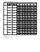
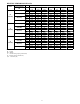

18
GUIDE SPECIFICATIONS
INDOOR CASSETTE DUCTLESS UNITS
Size Range: 3/4 to 1 1/2 T on Nominal Cooling and Heating Capacity
Carrier Model Number: 40MB*C
PART 1 - GENERAL
1.01 System Description
Indoor, in- ceiling, direct- expansion fan coils are matched with
heat pump outdoor unit .
1.02 Agency Listings
Unit shall be rated per AHRI Standards 210/240 and listed in the
AHRI directory as a matched system.
1.03 Delivery, Storage, And Handling
Units shall be stored and handled per unit manufacturer’s
recommendations.
1.04 Warranty (For Inclusion By Specifying
Engineer)
PART 2 - PRODUCTS
2.01 Equipment
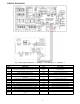
A. General:
Indoor, direct- expansion, in- ceiling cassette fan coil. Unit shall be
complete with cooling/heating coil, fan, fan motor, piping
connectors, electrical controls, microprocessor control system, and
integral temperature sensing.
B. Unit Cabinet:
Cabinet shall be constructed of zinc- - coated steel. Fully insulated
discharge and inlet grilles shall be attractively styled, high- impact
polystyrene. Grille shall have hinges and can be opened to obtain
access to the cleanable filters, indoor fan motor and control box.
C. Fans:
1. Fan shall be centrifugal direct- - drive blower type with air
intake in the center of the unit and discharge at the
perimeter. Automatic, motor- - driven vertical air sweep
shall be provided standard. Automatic motor- - driven
louvers shall be provided standard and shall be adjustable
for 2, 3 or 4- - way discharge.
2. Air sweep operation shall be user selectable.
D. Coil:
Coil shall be copper tube with aluminum fins and galvanized steel
tube sheets. Fins shall be bonded to the tubes by mechanical
expansion and specially coated for enhanced wet- ability. A drip
pan under the coil shall have a factory installed condensate pump
and drain connection for hose attachment to remove condensate.
E. Motors:
Motors shall be open drip- proof, permanently lubricated ball
bearing with inherent overload protection. Fan motors shall be
4- speed.
F. Controls:
Controls shall consist of a microprocessor- based control system
which shall control space temperature, determine optimum fan
speed, and run self diagnostics. The temperature control range shall
be from 62_Fto86_F(17_Cto30_C) in increments of 1_For
1_C, and have 46_F Heating Mode (Heating Setback). The
wireless remote controller, shall have the ability to act as the
temperature sensing location for room comfort.
The unit shall have the following functions as a minimum:
1. An automatic restart after power failure at the same
operating conditions as at failure.
2. A timer function to provide a minimum 24 - hour timer
cycle for system Auto Start/Stop.
3. Temperature- sensing controls shall sense return air
temperature.
4. Indoor coil freeze protection.
5. Wireless infrared remote control to enter set points and
operating conditions.
6. Automatic air sweep control to provide on or off activation
of air sweep louvers.
7. Dehumidification mode shall provide increased latent
removal capability by modulating system operation and set
point temperature.
8. Fan- only operation to provide room air circulation when no
cooling is required.
9. Diagnostics shall provide continuous checks of unit
operation and warn of possible malfunctions. Error
messages shall be displayed at the unit.
10. Fan speed control shall be user- selectable: high, medium,
low, or microprocessor controlled automatic operation
during all operating modes.
11. Automatic heating- to - cooling changeover in heat pump
mode. Control shall include deadband to prevent rapid
mode cycling between heating and cooling.
12. Indoor coil high temperature protection shall be provided to
detect excessive indoor discharge temperature when unit is
in heat pump mode.
G. Filters:
Unit shall have filter track with factory- supplied cleanable filters.
H. Electrical Requirements:
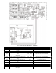
Indoor fan motor to operate on 208- 230V on model sizes 09 - 18,
as specified. Power is supplied from the outdoor unit.
I. Operating Characteristics:
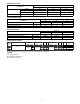
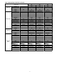
The 40MB*C system shall have a minimum SEER (Seasonal
Energy Efficiency Ratio) and HSPF at AHRI conditions, as listed
on the specifications table.
J. Refrigerant Lines:
All units should have refrigerant lines that can be oriented to
connect from the left, right or back of unit. Both refrigerant lines
need to be insulated.